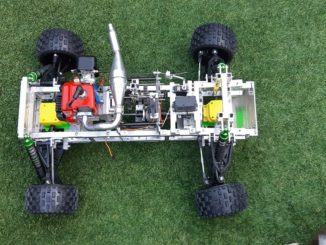
Welcome back to Cnuteneering, where the possible is made more difficult by bone headed ignorance, overenthusiasm and pointy metal things being brought together.
It’s been a very long while – you may want to refresh your memory on the project in:
Design goals:
Fast as possible on offroad; too big to have on roads. I will set a target speed of 50mph.
4 WD.
Must be able to reverse, and brake.
Unbreakable, or as close to.
Must be able to mount GoPro or similar camera on it.
Cheap as possible.
We left the last episode of Cnuteneering with the following items outstanding to be fixed:
• Petrol tank leak
• Move gearchanger to 3 position switch on Tx
• Throttle/brake servo calibrate
• Switches to pi and rx power feeds
• End point adjustment for servos and control mechanisms
• Pi case has a split
• Does the engine still start?
Once again ensconced in the Shed of Hope, I address the list of stuff to be fixed. The engine does not want to start at all, which is quite possibly due to the fuel tank leak.
Two stroke engines push excess fuel back into the tank to pressurise it and force petrol back into the engine, with a high pressure release valve also fitted so the tank does not go boom when the engine is running.
The engine does not seem to even be interested in turning over, so I check the spark plug.

As expected, it is filthy. I clean it up as best I can with some sandpaper and fit it again. I plug the spark plug in first, only to the cable and not into the engine, then pull the starter cord. A shocking experience indeed, so at least the electrics are working.
Below is the grommet that goes into the fueltank – you can see three tubes going in.

The top black one is the fuel line to the engine and has a weighted clunker with a filter on it so it sits and the bottom of the tank. The clear-ish tube is the fuel return line, and the tube pointing towards the camera is the pressure relief gizmo. There is a hissing and bubbling coming from where the clear tube goes through the rubber grommet, plus some bubbling around the grommet periphery.
I replace the grommet and re-attach everything but there still seems to be a problem as the tubes have hardened and shrunk a little. A few pull starts though and the engine splutters into life! Result!
In the meantime there is some orderly ordering going, I now at least have some drawers to keep bolts and spares and so on in.

On the subject of order the wiring is getting a bit out of control now. The 11.1v battery is too juicy to power the 5v Rx and servos, so it goes through the BEC in the light blue oval in the picture below.

The issue is that the car is either all on or all off, which was a bit of a failing of the previous bonehead who installed the wires. If you follow the red arrow, that is the 5v feed that is split on the left and right so that the blue lines show power to the Pi and the green lines show power to the Rx.
The Pi, being Loonix based, does not like just being switched off as the file system can become damaged. You have to tell it to shut down politely to avoid this. So when I am just testing the car, it’d be good to have just the Rx powered and not the Pi as well.

It does look purty though in the dark!
I need to make a splitter with the correct plugs so I butcher 2 servo extender cables together. This does leave a live 5V tail hanging off the Pi though, which may come in handy later.

And now have the 2 switches fitted so the Pi and the Rx power are independently switchable.

Next up I need to move the gear selector from Channel 5 (a rotary knob so finding first, second and neutral is a bit of a gamble) to Channel 4 which is a 3 position switch.
Getting the Rx bay open so I can get the Rx out is somewhat fiddly and tiresome, it is really tight in that area of the car.
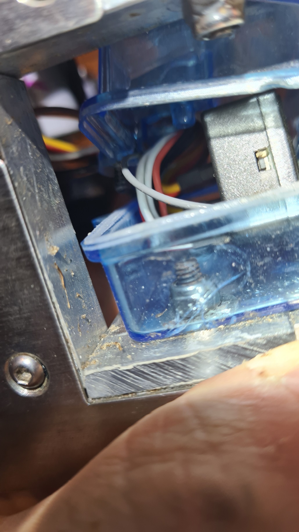
I manage to get the top off in the end, and can now move the servo cable from Channel 5 to 4 on the Rx box.
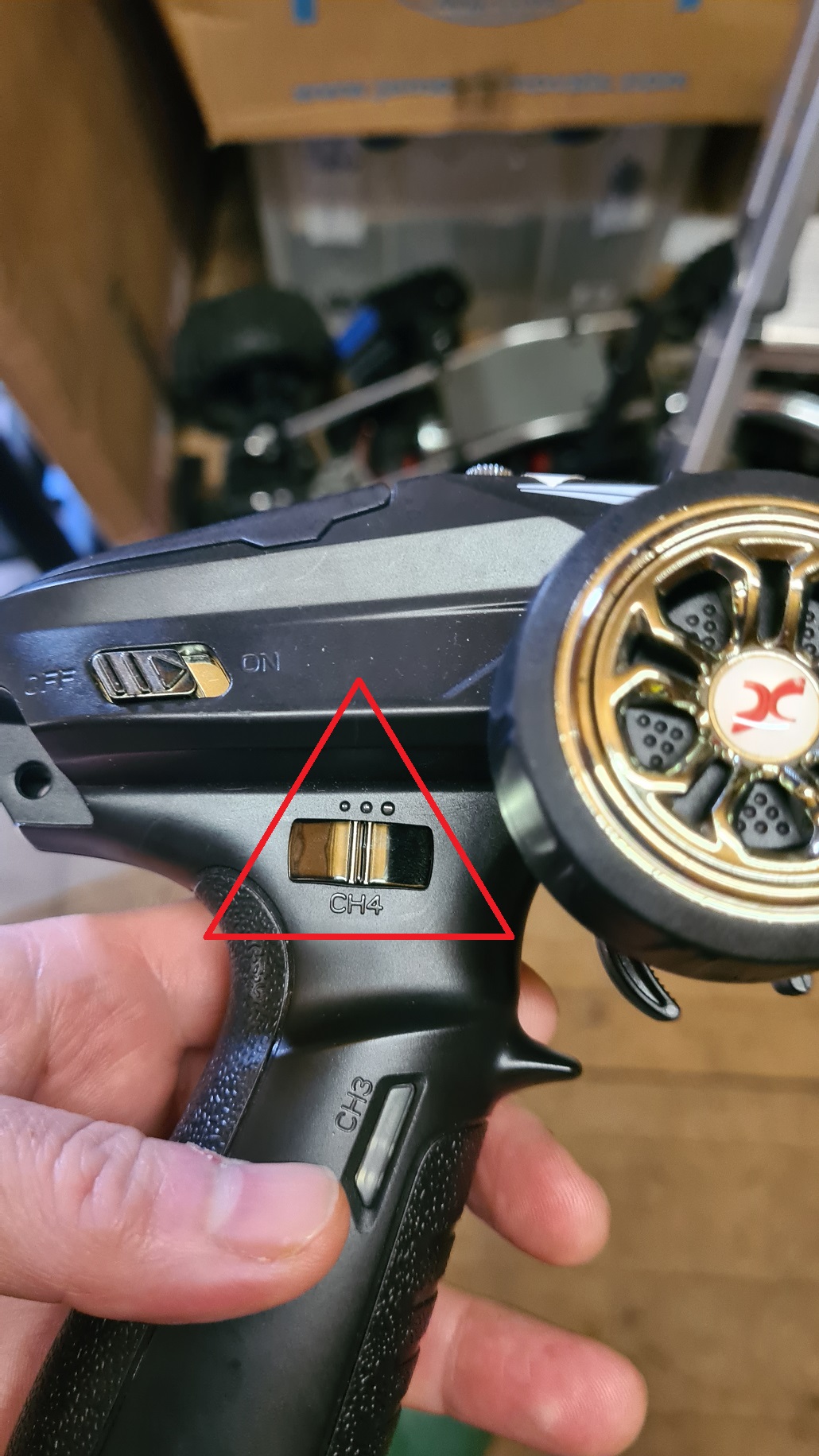
There is some Chinglish translation needed on the TX manual so that I can adjust the throw of the servo according to position 0, 1 and 2 on the switch. That link I have been nursing for over a year (Dumbo RC Setup https://www.youtube.com/watch?v=Sk6yh_Q2O6g) was luckily still working so some small faffing and the servo is set to max adjustment.
No idea how it determines it, perhaps it is relative to the adjustment limit, so switch in middle position servo is at 0, switch either forward or back is + or – adjustment limit. I just cranked it to max and let’s see where the die falls…
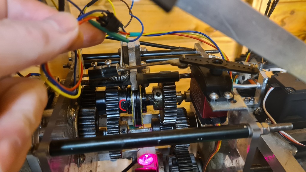
Now that is done, I can look at the other servo adjustment.
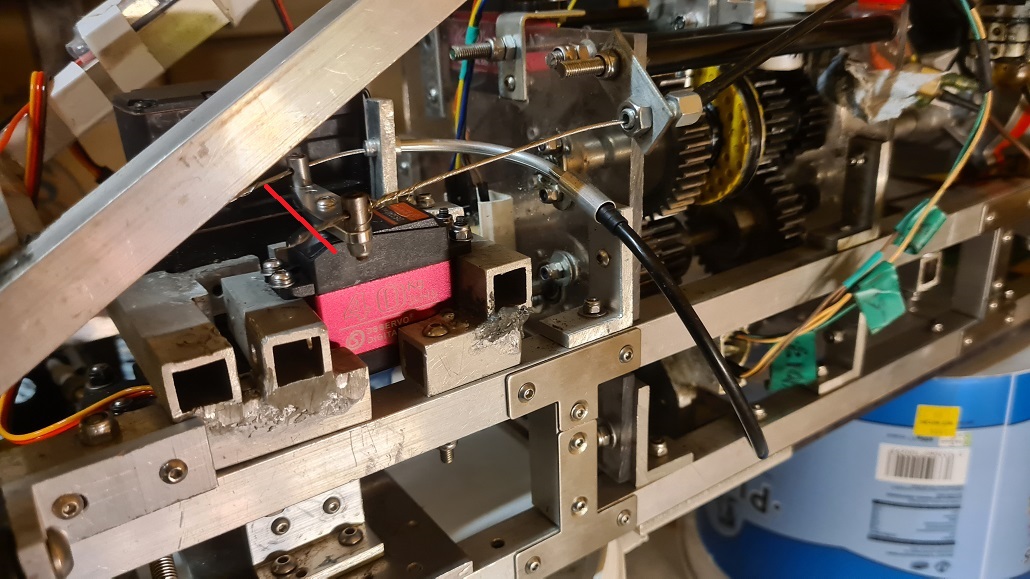
In the above the red line is parallel to the servo yoke that has the brake cable on one side (it goes through the curved metal tube) and the throttle line. There is a little grub screw holding the cable in place.
And now we can see if the gears are switchable in reality:
I cut the brake cable just so and it slides through the aluminium support I machined in the last episode, with a little (shamefully oval) pocket to sit in.
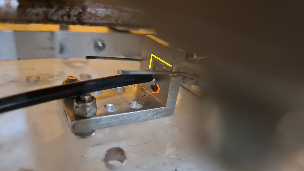
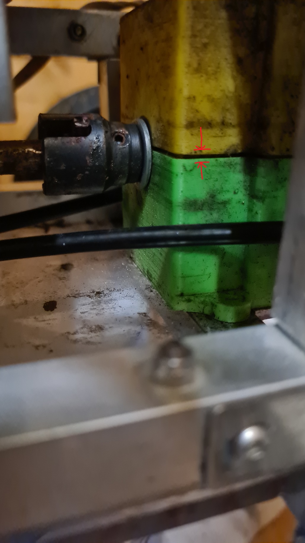
Everything is a bit cramped in that area of the car though and a problem soon shows up. When the brakes are off, the brake cable nestles on top of the brake assembly rest as highlighted by the red line
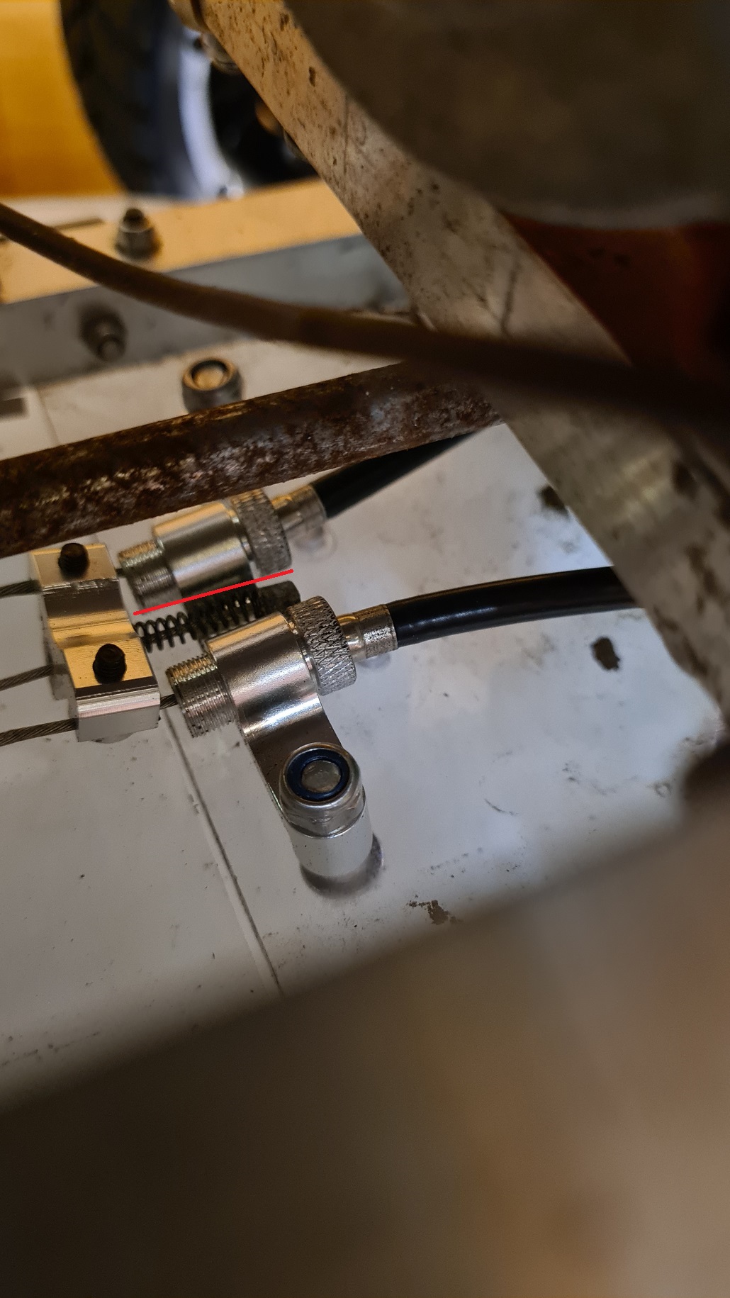
However, the end of the cable gets stuck on the brake assembly rest, so the brakes remain on.
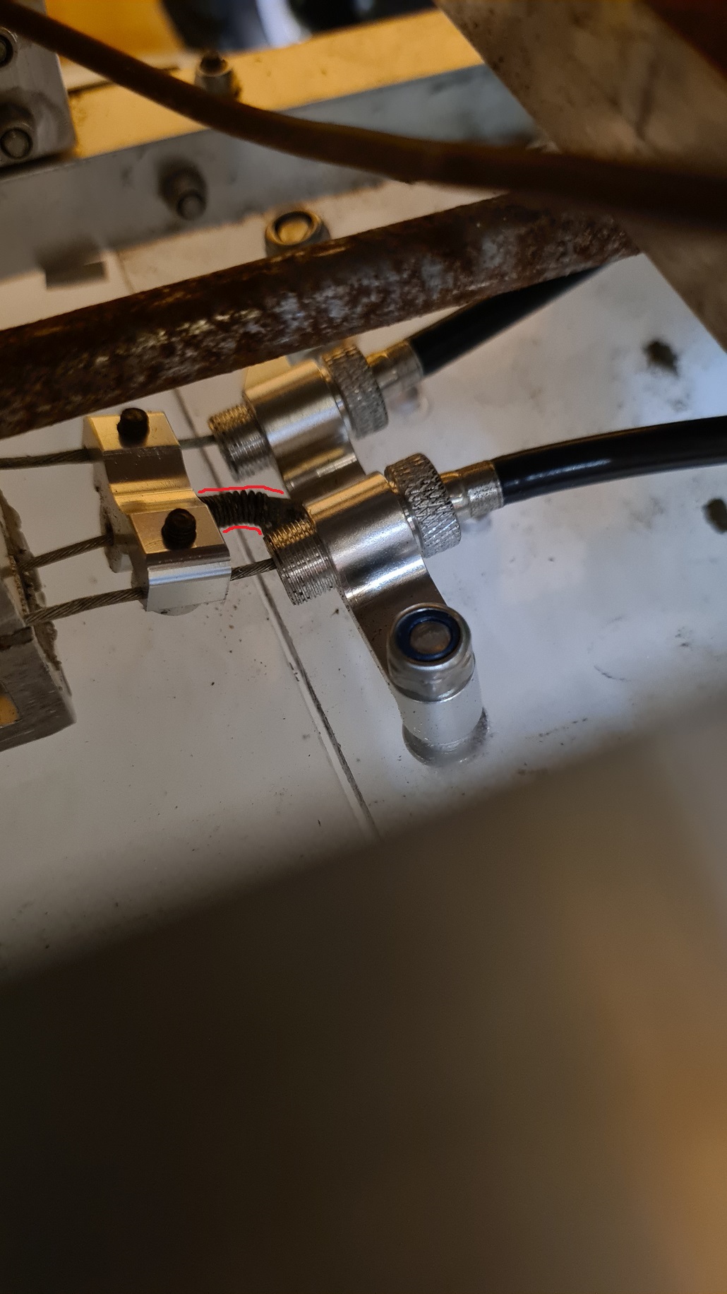
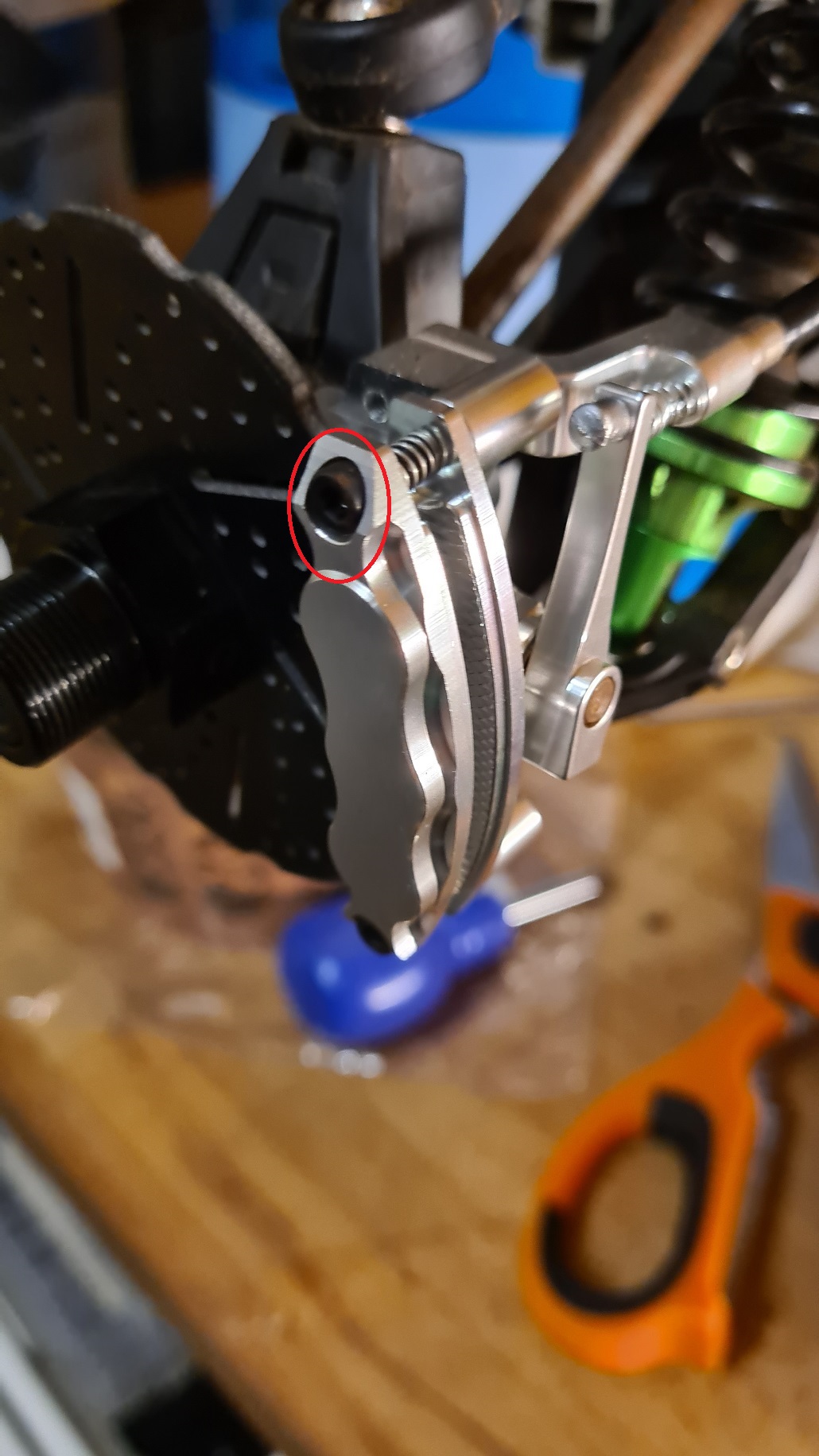
There also seem to be some adjustment bolts on the brake shoes themselves, that bolt got “lose me in a field soonest” written all over it. I adjust them a little so that the brakes are off when the brake cable is at rest.
And now we turn our attention to the gearboxes, as I have been fettling about the car I notice that the cases are cracking open a little and this is not only bad as it lets water and dirt in, but it also allows the gears to ride up over each other.
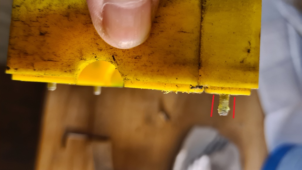
I take the rear gearbox out and note that the pitifully small M3 bolts seem to have sheared the thread, judging by the cruft in the thread in the pic below. The threads on M3 are quite delicate and I reckon the ABS that the gearboxes were printed in is just too weak to handle it. I will need to put M4 bolts in I think.
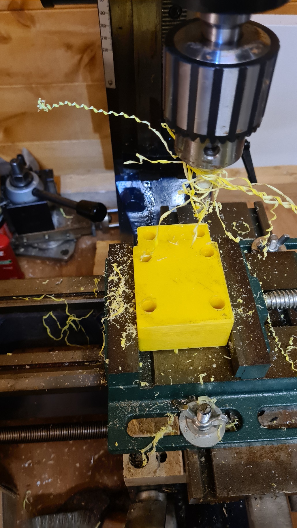
M4 bolt heads are of course, a fair bit more chunkeh than M3 so in order to get them in I will need to fire up the milling machine to widen them a bit.
And it is at this point that I remember why I used wimpy M3 bolts – the clearance is too tight in the interior.

Overdrill!
As you can see in the above there is now a breach into the main gearbox chamber, so any water or dirt can fall into the access holes and bounce straight into the gearbox itself.
Bugger.
I tape over the holes from the inside and offer another prayer to the Gods of Cnuteneering.
Rinse and repeat with the front gearbox, wincing as the chamber is breached again.
I do get to do some proper milling though this time, only to find that the drill press vice is utterly shit. I really am going to have to sort out the proper vice I have sitting in a box here…
Still, it is considerably quicker having the right tools for the job, and being able to have several drills on the go – the bench drill press, the milling machine and the battery Makita I can drill the 3.2mm holes to accept the thread for the M4, drill the 4mm holes and the pockets in the gearbox without having to keep changing the drill bit over in one drill. The Shed of Hope is truly a haven!
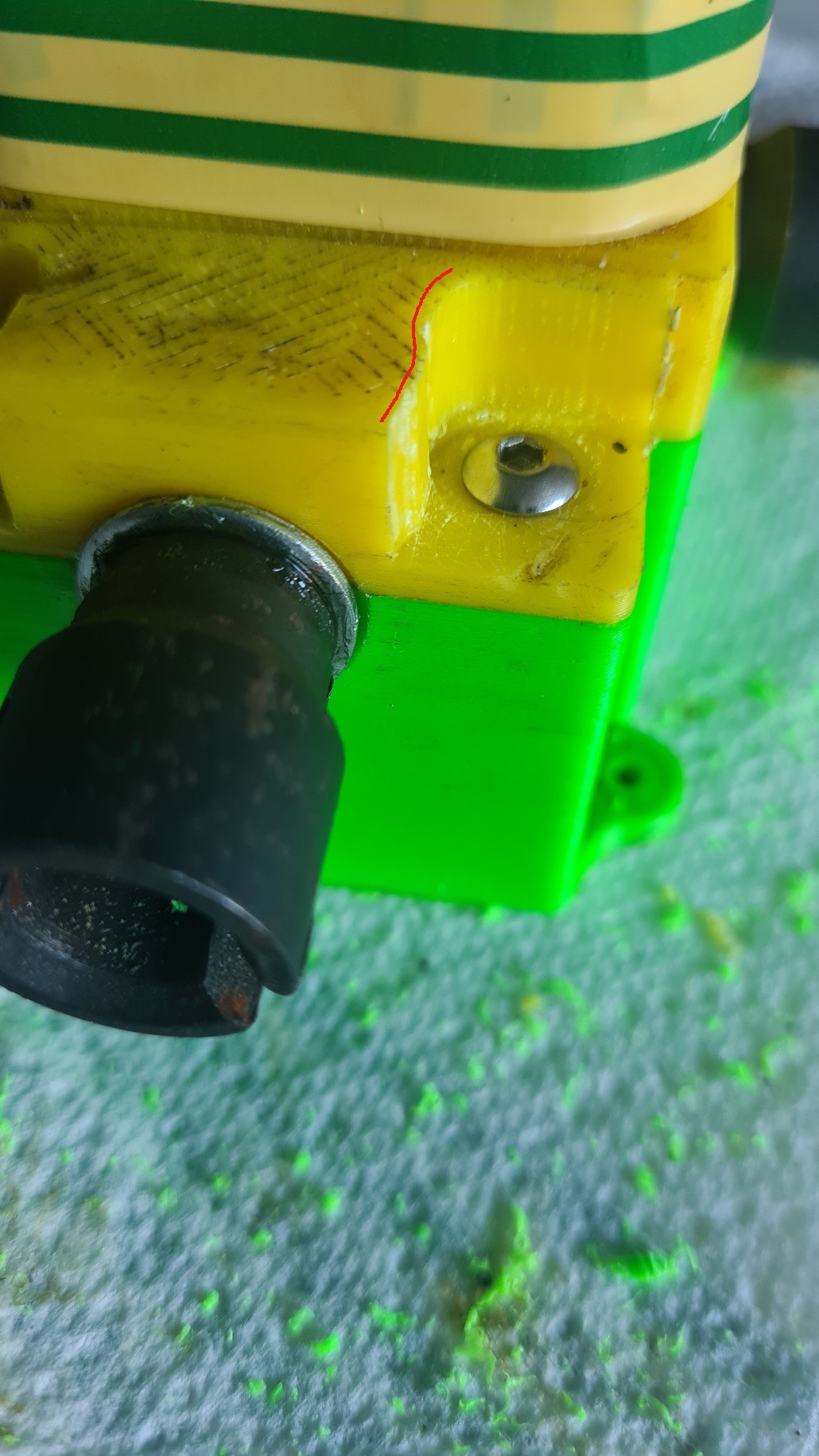
Not content with the internal taping, I also tape over the holes from the outside and finish with a rather fetching frapping turn of tape around the box in an on-trend yellow and green earth insulating tape. Simpleh divine accesorisation, dahling!

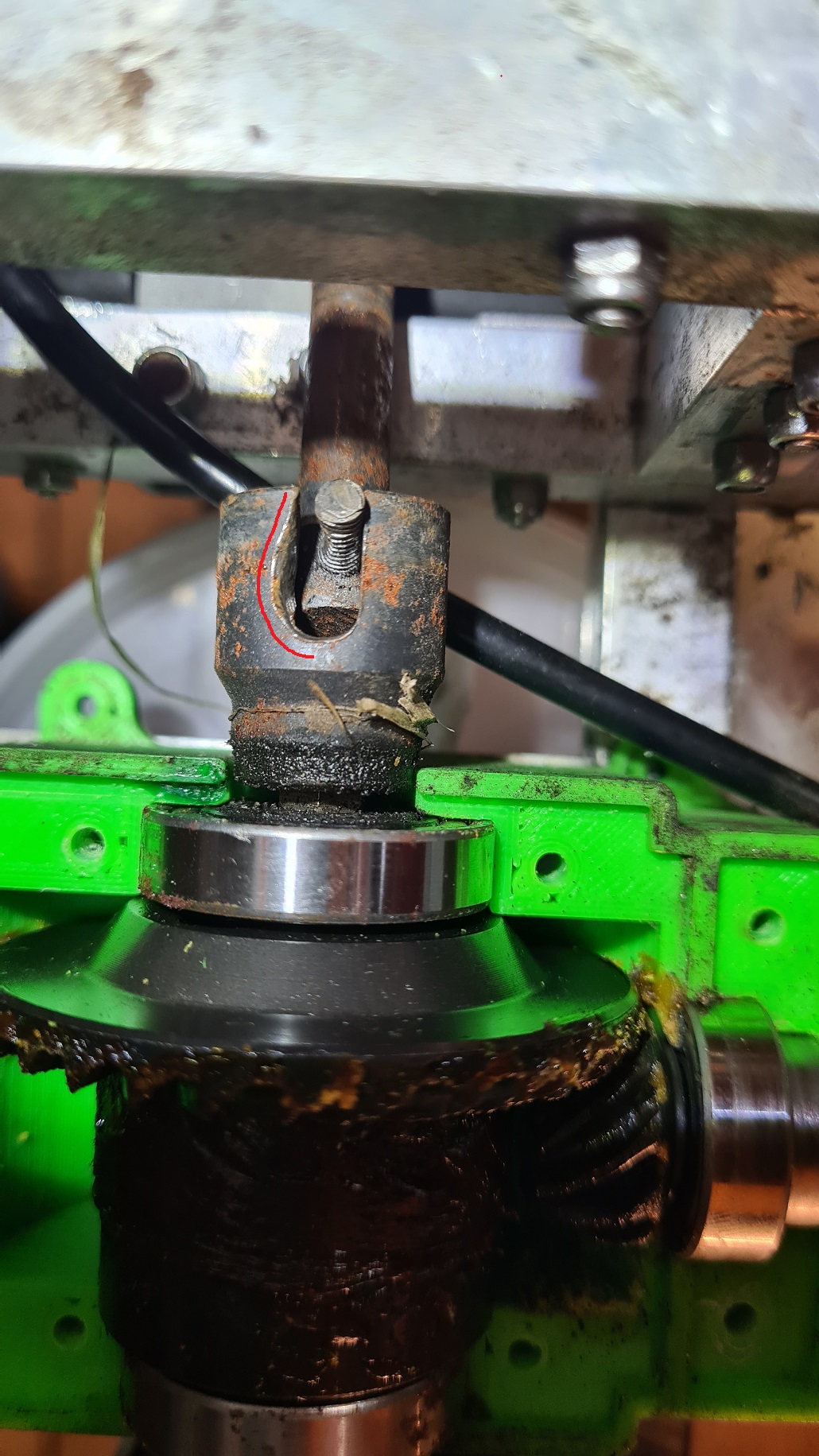
Although it does look like there is trouble ahead with the wear on the drive train sockets.
Now that everything electrical seems to be in the right place, I can put the Rx box back together again. I also add cables for channel 5 and 6 for a reason we will see later in the series…
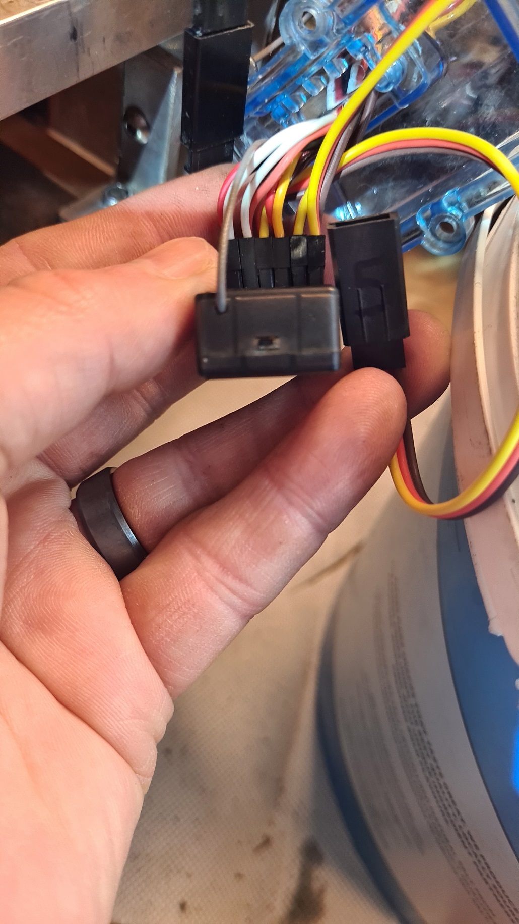
Getting the Rx box bolted back together is really quite tiresome, I am sure I have taken this picture before…
I feed the spare channel cable through the box opening and label them carefully. This also protects them from water and mud.

Observant puffins will notice that channel 3 is unused – this is where I am putting the power for the Rx into the unit. I hope this does not come back to bite me later.
Now that everything is back together from a control servo perspective, I need to sort out the brake recoil mechanism.
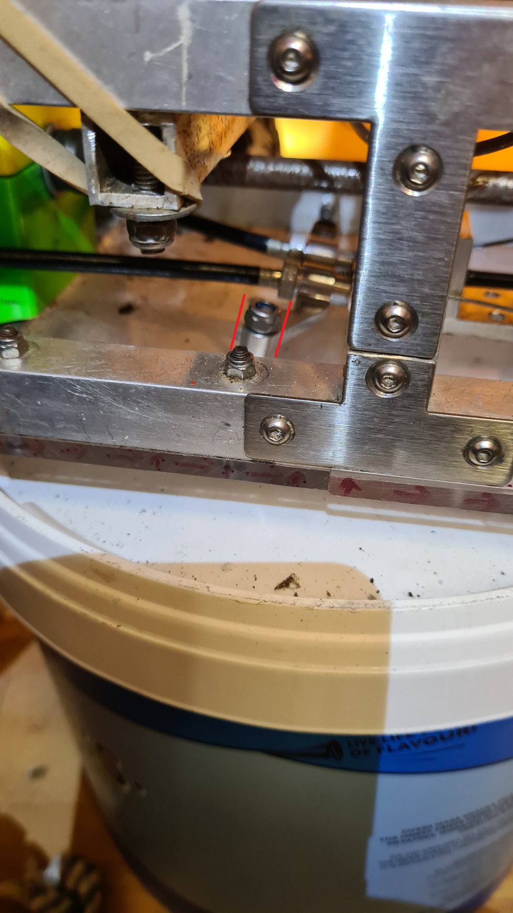
More trouble, the brake mount thing is clearly tilting forward when the brake cable is pulled.
I end up having to redrill the mounting holes for the brake cable stop (the bottom of that part of the chassis is now looking more like a cheese grater than an underplate, but this is the price of iterative design!) and fit a little wedge of polycarbonate block under the hoop of the brake hoop.
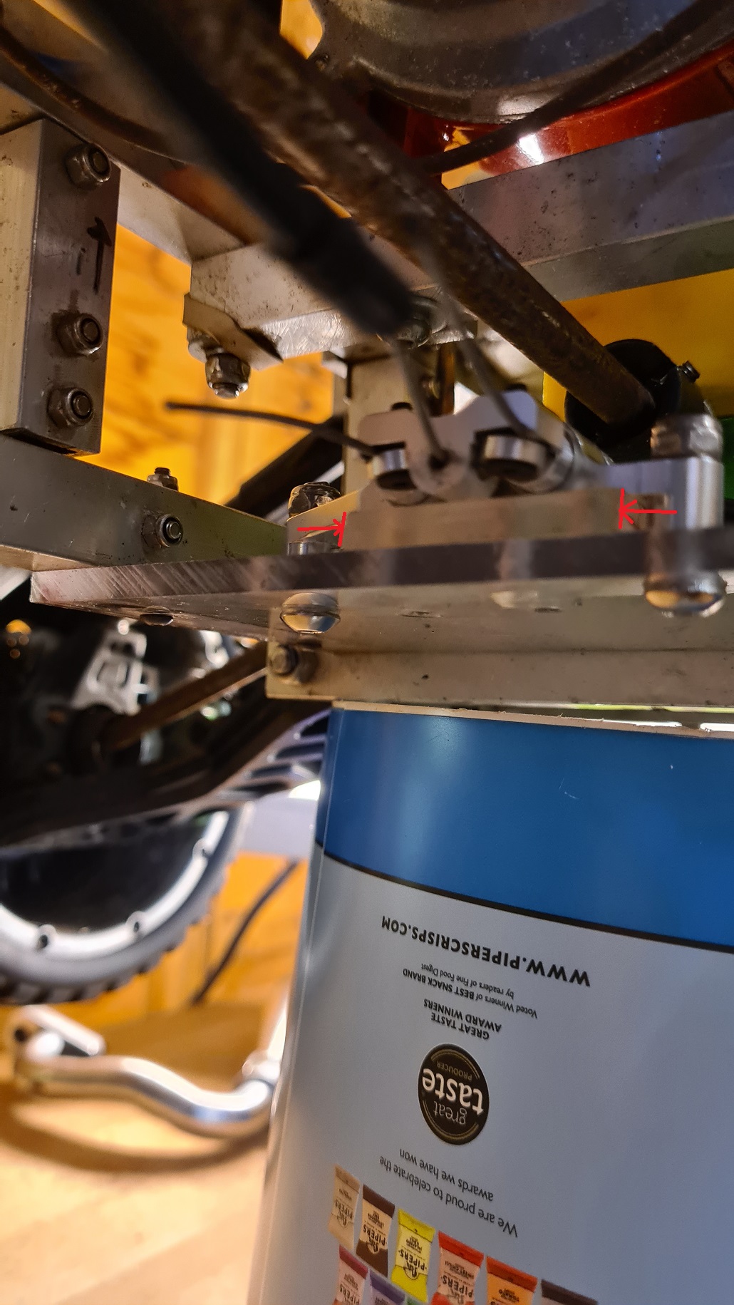
Hopefully that will be enough to hold it.
I can now fit the race can exhaust, which is not awfully straightforward. Again.
The new position of the motor sensor is in the way of the exhaust pipe, which is annoying.

This is likely going to get toasty hot and burn the signal cables to the sensor, which would be somewhat problematic.
The trusty Dremel comes out to save the day:

And now if I strap the exhaust up a little with the copper wire out of some electrical cable, it should have enough clearance I hope.
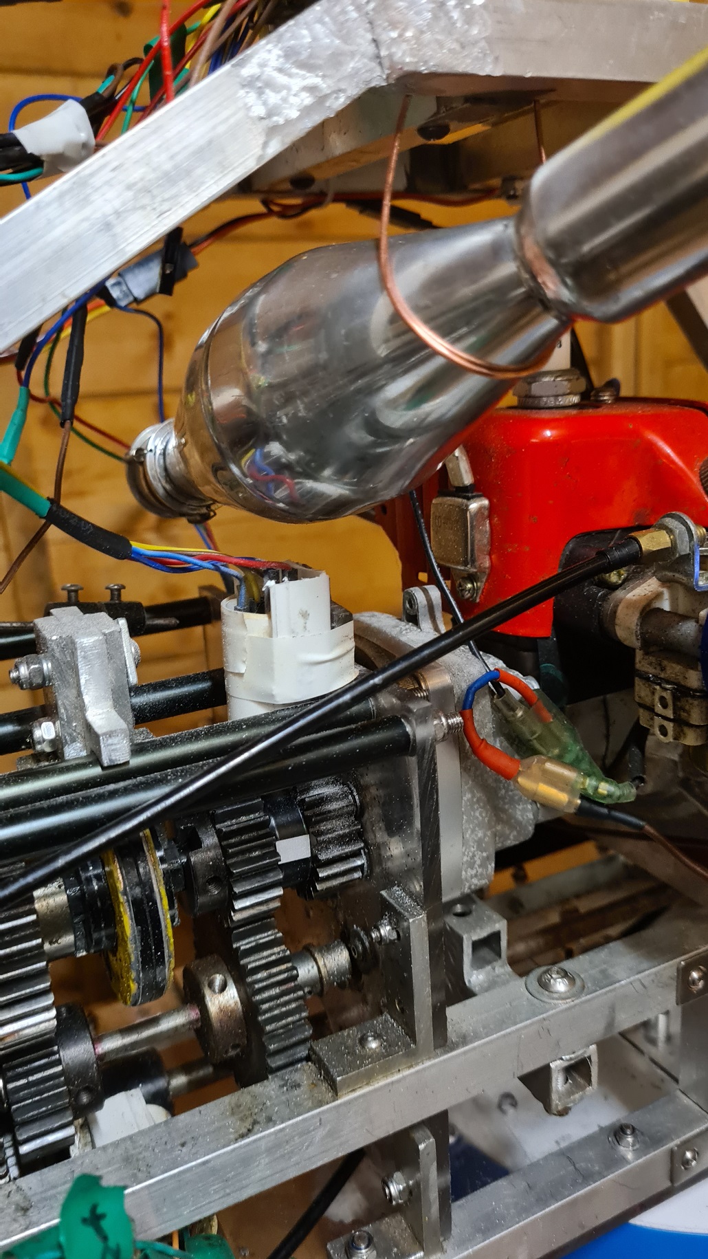
That’s it, the car is properly rebuilt, all niggles are sorted out and so it is ready to take out into the Field of Testing And Despair to see how it performs.
There are of course, other pressures on my time so it will have to wait until next episode…

Still waiting for:
Still left to do / think about
Body shell
Look at how Root superchargers work
Pics, vids, words and music © El Cnutador 2023


