
Welcome back to Cnuteneering, where the possible is made more difficult by bone headed ignorance, overenthusiasm and pointy metal things being brought together.
You may want to refresh your memory on the project in:
Part One.
Part Two.
Part Three.
Part Four.
Part Five.
Part Six.
Part Seven.
Part Eight.
Part Nine.
Part Ten.
Part Eleven.
Part Twelvety.
Part Thirteen.
Part Fourteen.
Part Fifteen.
Part Sixteen.
Part Seventeen.
Part Eighteen.
Design goals:
Fast as possible on offroad; too big to have on roads. I will set a target speed of 50mph.
4 WD.
Must be able to reverse, and brake.
Unbreakable, or as close to.
Must be able to mount GoPro or similar camera on it.
Cheap as possible.
We left the last episode of Cnuteneering at the low point of despair and self pity. A few days off and some Dogtime and the Loneliness of the Long Distance Cnuteneer was lifted.
In terms of Dros Delnoch we have moved from Musif – Despair to Kania – Renewed Hope. Let us hope we don’t get to Sumitos.
I have taken the decision to mount the suspension arms on the bottom of the chassis, weld the central blocks (carefully!) and bolt the front and rear crosspieces. This means I can easily remove the suspension arms for maintenance, and the central blocks are not in the way of the support for the drive socket. These are flat 90 degree to flat welds so should take quite well I hope.
Aside from trying to braze outdoors, in the wind and rain, another challenge I face is the lack of any kind of consistency in strength. Critics would argue that I should add lack of skill, talent and ability to that list, and I would probably agree with them.
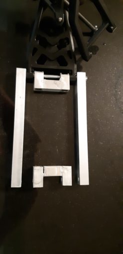
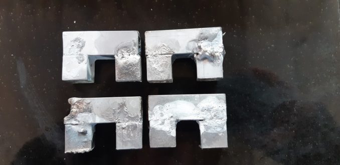
I am still not having much luck with the brazing, as we can see above where the central block clearly has a gap between the pieces after I cleaned it up. But at least you can see how the blocks fit together to hold the suspension arms, and the long M6 coach bolts are nicely the right size. The end box sections will be bolted to the chassis so they can be removed if needed for maintenance and repairs. I have to be quite careful as I put stuff together now as I know in the future I will be taking it apart again, and it’d be nice to be able to replace a part without taking the whole car apart.
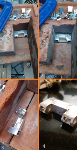
In pic 1 above my makeshift brazing table is holding the three pieces I need to attach to each other. One thing I have learned is that being outside really strips the heat from the aluminium making the brazing even harder. Pic 2 shows a little overenthusiasm with the solder and it has pooled in a mess all over the joint. I tried to re-heat it and encourage the excess solder off it but instead ruined the piece as per pic 3.
A little more patience and with less wind blowing about my ears, I managed to braze it all quite nicely and clean it up ready to be used as in pic 4.
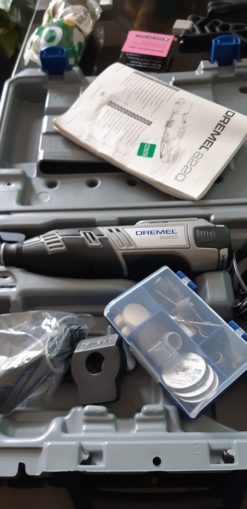
More regular puffins will know that I recently had a birthday, for which MBWKaren presented me with this little beauty:
I have long been desirous of one of these but haven’t really got over the “will I _really_ use this often enough for it to justify the space in the shed?” barrier. Plus I was unconvinced of the power and capability of the device.
Well, I am converted.
How did I live my life prior to having one of these? It is light, manoeuvrable and has quite a bite when it gets going. The number of different purpose cutting heads that are available seems limitless – from mini angle grinders to drillbits to circular saws to polishers…
I would score it a 9/10 as a worth the money, it’d be nice if it had a reverse mode on it but I am very impressed so far. Probably not so much when I go to buy replacement heads, but for now I am enjoying using it. Filing down tasks that would have taken me over an hour – done in 10 mins.
Result!
Right now the plan is to braze the end pieces across the chassis lengths to get a feel for how things fit together. These will be rectangles, one on top of the other that are bolted together and the flat 90 degree plates and T plates have already arrived. This is so I can take it apart and fix it, plus I really do not want to be brazing with the engine and petrol tank right next to the joints.
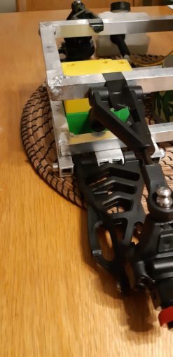
For now, the top suspension arms are just taped to the chassis as I have yet to decide how they are to fit to the top rectangle. The top and bottom arms need to be as close to parallel as I can make them so the travel doesn’t try to move either the top or bottom chassis rectangle. I had hoped to have them either mounted above or below the top rectangle but it would seem that central is the way it has to be.
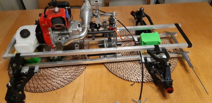
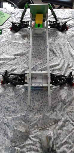
This now means I can start putting the car together properly for the first time – the engine and gearbox are sorted bar some Nyloc nuts. I can focus on starting at the back of the car, and attaching things as I go forward /fingertips together, push out/ on the chassis.
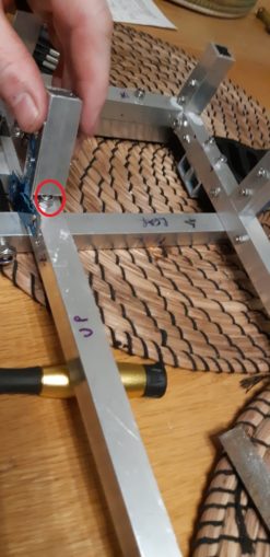
This is a close up of the Follymobile’s rear end, filth etc. As you can see all the manhandling of the chassis rectangles has weakened the braze and it is starting to come away. For some reason, these 45 degree cuts seem really hard to get to full strength. I don’t know if it is because for whatever reason the nature of the angle means heat is hard to concentrate on the join, or if it is because they are brazed without the brick enclosure I have been building for the smaller parts, which also keeps the heat in.
I am going to give it one more go but using the bricks this time and then either try a 90 degree braze or just put an angle bracket in and bolt them together. Bolting them together is going to be difficult in itself as there will be a lot of competition for space with the fixings on the corner of the car. Too many bolts and not enough area to fit them in.
On the plus side, the gearboxes fit snugly and I should be able to fix them securely if I put a bottom plate under them. Because the bottom suspension arms are below the lower chassis rectangle now, I have clearance to mount the plates across the full width of the frames, to the outer edges rather than the inner edges. This will make the attachment easier I think, and it will be easier to maintain.
I will need to do this under the gearbox, too, so that there is something for the central diff support to attach to, and in turn the front differential. 6mm plate will be good for attaching, but for the gaps in between I think I will get a sheet of either polycarbonate or carbon fibre to lay over the top to make a smooth surface front to back.
Looking at my other cars, they seem to have a little upturn in the chassis so the front suspension arms are higher at the front than at the back. I am a bit lairy of bending the aluminium as I fear it will weaken it somewhat, but I can’t think of what else I can do. Perhaps a guard plate on the front, from the front suspension arm holder to the main bottom frame, that would be at an angle at least. Further thought needed I think; I can deal with that once I get to the front of the car.
As the top suspension arms need to be level with the top chassis rectangle, I can’t repeat what I plan to do for the bottom; I must make some C brackets that I can bolt through the chassis vertically, that can then provide a horizontal hole for the suspension pin to run through.
Accordingly, I cut, file, clean with acetone all the pieces to make four C shaped brackets. In total, this is about four hours work. Eventually, wind and torrential rain in my luxury custom fitted workshop back patio abated enough for me to manufacture the pieces.
In the course of making these though the trouble was brazing one end piece on, and then have it melt and fall off while brazing the other end. This has forced me to reconsider how I should attach the central blocks for the rear suspension; brazing is almost certainly out.
Quality is indeed variable with the brazing and I really cannot understand why one braze takes nicely and the other does not. Russians, most likely.
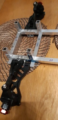
I am quite happy with the way the plan looks now so I can get on and start fitting the rear suspension assembly to the chassis, and installing some uprights that will sit between the bottom and top rectangular frames.
What with all this cutting and brazing and making of small assemblies, despite almost no wastage (about 30 cm as far as I can tell) I have gone through ~6.5 of my 8 metres of box section. This is a little alarming as I still have yet to design and build the main canopy and I would have only enough to replace one of the long pieces that make up the chassis frame if I need to. In any case I can start bolting it all together at last!
Now I can get on and build the rear shock tower to attach the shock absorbers to, and try to fit the petrol tank in nicely. 4mm aluminium plate should be good for it I think, which I already have being one of the first things I bought so long ago.
As I choose where to place the upright, I do wonder if I have made myself a hostage to fortune with the placing of this – the nut that retains the suspension mount is hidden in the upright itself. Time will tell, I am sure!
In a chat with my Braheelian engineer mate, he mentioned the use of angle aluminium instead of making all the parts for a bracket. Obviously, this was after I had made them, but at least two of the C brackets are going to fall apart when I use them and one is melted badly. A length of 1”x1½” x 3/8ths L section could be had for a tenner, so off to Aluminium Warehouse where my carefully crafted order just tips over the 40 quid starting blocks if I order another 4m of box section (these guys are the only ones I could find that do 2mm thick walls) so I can place an order and get skinned ~13 quid for delivery.
While I was fettling with the Pi telemetry stuff I realised I had only ordered two of the sensors to see if I could get them to work. Obviously I need 3, one for engine RPM and one for each side of the central diff. Lucky I soldered in that “extra” control pin and power then, eh?
Another pack of 2 sensors ordered, and we’re back to my favourite part of the project, waiting.
Making progress again though, a little bit of drilling, bolting and fettling of the shocktower left to do and the back end is structurally complete. For once, the pile of THTTARN has decreased in size this episode.
Still waiting for:
Angle aluminium, more aluminium box section.
More RPM sensors.
Still left to do / think about
Sort out the car underside – at the minute it is just a gaping void
End point adjustment for servos and control mechanisms Dumbo RC setup
Siting of brakes
Need to build the brakes as well I think!
Finish RPM counters
Siting of RPM counters
Integrate code to read sensors, temperature and RPM into the video capture
Front end siting of servo and steering yoke
Siting of battery and control gear
Bend the front of the chassis up or not?
Pics, vids, words and music © El Cnutador 2021
The Goodnight Vienna Audio file


