
Welcome back to Cnuteneering, where the possible is made more difficult by bone headed ignorance, overenthusiasm and pointy metal things being brought together.
You may want to refresh your memory on the project in:
Part One.
Part Two.
Part Three.
Part Four.
Part Five.
Design goals:
Fast as possible on offroad; too big to have on roads. I will set a target speed of 50mph.
4 WD.
Must be able to reverse, and brake.
Unbreakable, or as close to.
Must be able to mount GoPro or similar camera on it.
Cheap as possible.
We left last episode of Cnuteneering with the arrival of the drill press. Also arrived was a small bench vice. A little bit of assembly required and voila – some semblance of orthogonality all the way though the box section.
New thing learned – metal appears to like it better when the drill is not at full speed. About 1/3rd of full beans is about optimal for this aluminium it seems.
The endless saga of the Non Arriving Pinion Gear still continues, having laid out the gears on to the polycarbonate sheeting it is clear the the placing of the first gear is going to really shift how the rest of the gears are put together. It has also become clear that I need a really good understanding of exactly how far below the engine the drive shaft needs to be in order not to foul. As posited in the last episode, I do have a workaround but it’d be nicer to have everything just so; I am hanging back with the angle grinder and 6mm drill. Stalled again! (shakes fist at sky). Nine more days, at the time of writing.
I still need to be able to change gear though, so that is at least something I can work on for now. Keen readers and those without rotted memories from #FF excesses will remember this picture from the last instalment, of how the gears fit together and the gear change mechanism is to work:
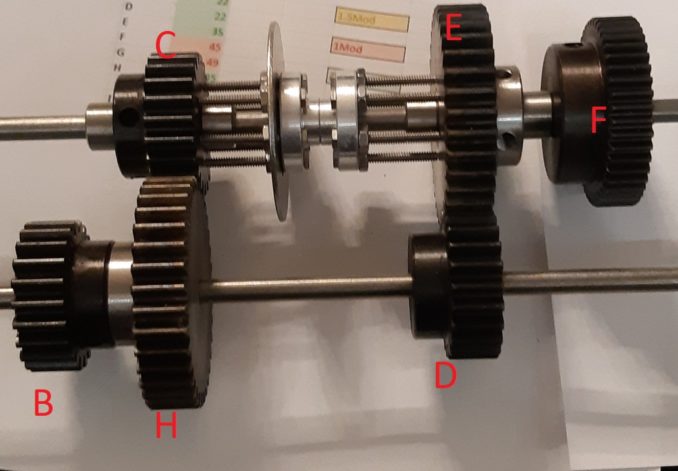
I need something to push and pull the dog tooth gear linearly (that’s the assembly between gears C and E with the giant washer). I am guessing that the teeth will bite into the mounting holes on the gear as the throttle is increased, which could lead to a partial mating of the dog teeth and their recesses which will stress the dog teeth unduly. The faster the engine goes, the more force holding the teeth in place will be. So I need something that will exert constant pressure against the dog tooth gear once a gear is selected, to force it into place. Given that the gear change is going to be clutchless it will need a little bit of finessing on the gear changing and how hard the throttle is pulled.
I could rely on the servo to exert the force but they really don’t like being strained, pushing against something that has little give in it for a long period. I need something that will push constantly, independently of the servo.
And here we have the gear changer Mark 1 design:
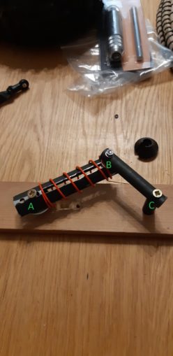
Points A and C are fixed, for now on the trusty Bit Of Spare Wood From The Shed. At each point, A, B and C the mechanism is free to rotate. The red spring pushes out so A –> B is always at the maximum unless force is applied. If I attach some kind of follower guide that has a guide each side of the dog tooth giant washer, it will snap the dog tooth gear either left or right.
Following the line from B to A, the rod AB should be longer, extending past the pivot point A. This is where I can mount my servo, probably with a spring attached. So the servo will turn, pulling the spring to extend until it is too tight, and then the mechanism will snap to either one side or the other.
Unfortunately I only had the short bit of material for AB so it is incomplete as is. The channel that pivot point B is in was made by drilling a series of holes in a line, then cold chiselling and sanding them out. What is clear is that the edges need to be perfectly straight for good operation, and the material needs to be quite strong. For this I will need the use of a milling machine.
Overall though as a proof of concept I am pretty happy with the way it works. It will need miniaturising and building properly however.
While all of the pinion gear shenanigans have been going on, I chanced upon an ebay sale of great import. I luckily won the auction and got these lovely parts for about 100 quid. Some guy was breaking an HPI Baja up for parts and these were all brand new:
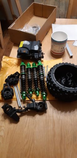
Finally things begin going my way! At the bottom left there are the hub carriers which go into the wheel axles (which I already have had for some time). Next to them are some metal rods which fit through the carriers and attach them to the suspension arms, front and rear shock absorbers and most usefully of all, a black plastic box with space for a receiver and crucially, two servos. One for steering and one for throttle. The box is waterproofed, which is a total result. I do not know if I am making myself hostage to fortune though, as HPI part availability was one of the drivers for starting this project…
I had planned on machining the hub carriers myself but frankly I could not have bought the raw aluminium for what I paid for the plastic equivalents. Which also include bearings that fit snugly. So I have satisfied one design goal (cheap) at the expense of another (self build). Tradeoffs, eh? I have likely saved a good four days of effort though so I am putting that firmly in the WIN column. Which is better than many of you did for Cnuteneering in the Autumn GP competition!
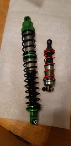
In previous weeks I thought I could repurpose a repaired set of Vorza (1/8 scale) rear shocks for use as front shocks. Here you can see the foolishness of that idea – green shocks are the new ones I just bought, red for the Vorza’s.
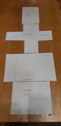
I now have a whole load of known knowns, so with my pioneering 3d modelling system, I can get a feel for how big everything needs to be. Fuel tank at the rear, then the engine, gearbox, receiver and servos. The receiver / servo box has mount points either side, and these look like a reasonable width to aim for, for the main front to rear parts of the chassis. I reckon 85 cm long which will allow a bit of to-ing and fro-ing plus enough to bend upwards at the front to make a bumper. I won’t machine anything yet until I get a feel for the balance – ideally I would like the balance of weight to be around the centre of the car, which might mean a bit more faffing about to get right.
Now that I have the chassis width, I can defer deciding the car overall width until I get all the transmission parts mounted on to it.
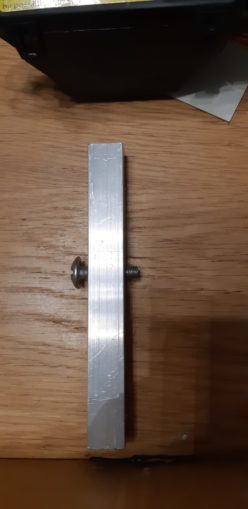
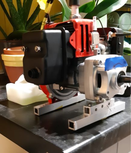
It does mean that I can put the engine on a proper Cnuteneered mounting block though. My hacksaw skillz need sharpening up, or I need to find some better way of cutting accurately.
And so, back to my most regular part of the project: waiting for a pinion gear to arrive.

At least these lists are getting shorter…
Still to be designed
Rack and pinion for gearbox servo?
Rack and pinion for steering servo?
Suspension arms
Brakes / reverse gear
Still needed
Pinion gear clutch bell should have been here between Oct 27 – Nov 16. This is late you bastards!
Servos x – one weakish perhaps <10kg? for gear select
Servo saver for steering – this breaks cheaply when you crash instead of the expensive servo gears.
Drive shafts from central diff to front / rear diffs and from front / rear diffs to wheels.
Pics, vids, words and music © El Cnutador 2020
The Goodnight Vienna Audio file


