Welcome back to Cnuteneering, where the possible is made more difficult by bone headed ignorance, overenthusiasm and pointy metal things being brought together.
It’s been a very long while – you may want to refresh your memory on the project in:
Design goals:
Fast as possible on offroad; too big to have on roads. I will set a target speed of 50mph.
4 WD.
Must be able to reverse, and brake.
Unbreakable, or as close to.
Must be able to mount GoPro or similar camera on it.
Cheap as possible.
We left the last episode of Cnuteneering in November 2022 which seems a lot more recent than I had remembered. We have had the birth of Cnutelectronics in the meantime and the founding of The Cnuteneering Home For Wayward Lathes and Milling Machines (CHFWLMM) to contend with, essential home improvements, apathy, sloth, personal injury and insanity all competing to impede progress.
I was partway through the installation of the brakes that I bought, conceding that the electric motor I was going to use as brake and reverse were not up to the task and to replace them would be quite tiresome in terms of cost and faff. So onwards, smiling through the tears, as ever…
The list of faults so far:
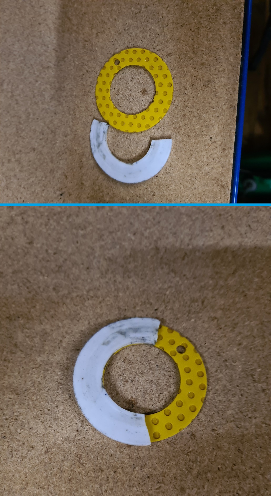
• Shattered PTFE thrust washer
• Fuel tank air leak
• Brakes not working at all
I manage to find the thrust washers, DU-B stylee that I bought in January /last year!/ to fix the shattered ones. I have no idea why the PTFE one broke – it is either due to the fact I was lazy when fitting them (OCD and autistic readers will recall I sliced a diagonal cut into them to slip them over the axle, instead of taking the gearbox apart and fixing them on properly.
With the bronze backing, there’s no way I can repeat this trick of laziness so I am going to have to take the gearbox apart and do it properly this time. Which obviously flies in the face of the finest principles of Cnuteneering, where near enough is good enough!
Unfortunately, the CheatMobile is currently taking up the workspace area in the CHFWLMM, so that will have to be fixed up first. There must be order!
The CheatMobile has a working engine, what is not working though is the “going forward” mechanism. Not a wanky buzzword bingo phrase, the engine turns, the front and rear driveshafts turn but the wheels do not. I strip the whole car down and crack open the in-the-axle differential gearboxen.

The rear diff has 4 little bevel gears that are sandwiched between bigger bevel gears that lead to the wheel driveshafts. As you can see, there is something of a “teeth not found” problem with them. This will need replacing.
The front diff has a different (hah SWIDT!) problem – it is not the internal pinion gears that are busted.

Instead, as you can see above, the actual teeth of the gear itself have been brushed over. Instead of neat parabolic curves we have a breaking wave side profile.
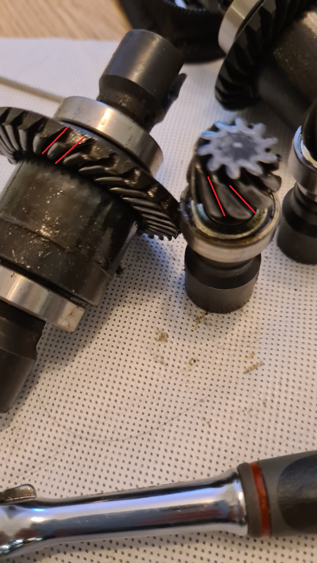
This problem affects both pinion and spur gear. No option but to replace. I did think to use the still functional spur gear to swap out with this one, but on counting the teeth, there are mismatches.
Rear diff was a 12 tooth pinion gear (the little one) and a 37 tooth spur gear, the front is a 10t/32t combo. The front gear was an aftermarket 4wd upgrade that I bought and did not count the teeth on the existing rear. So for the spur gear on the front to make a full rotation, the pinion will rotate 3.2 (3 and 1/5) full rotations.
On the rear, one full rotation of the spur gear is 3.083333 (3 and 1/12) pinion rotations. This mismatch is obviously a cause for stress in the system.
So I ended up replacing both front and rear diff gearboxes. I think this means the top speed will be less, as for one pinion revolution on 12t/37t it will drive the spur 0.3243 turns, on the 10t/32t the spur will make 0.3125 turns. Given the max rpm of the engine stays the same, the top speed will drop off.
I should get a little improvement in torque and acceleration though. How much torque, acceleration and max speed are going to change in observable terms though I think is going to be hard to discern.
I fit the much happier looking gear and put the gearboxes back on the car.
While not paying attention, I have fitted the diffs the wrong way in the gearboxes (so the car tried to go backwards!) and the chassis got a little torn up. No harm to the gears themselves, so I flip them over and the CheatMobile is once again fixed and ready to race!
Or, at least, be shuffled off the bench so the real work can begin.
The CHFWLMM set up is slowly getting there. I need to mount some hooks on the walls, find the baskets to go in the racks under the workbench, clean and fit the benchvice that has been shamefully allowed to rust outside and so on but at least I have somewhere to work.

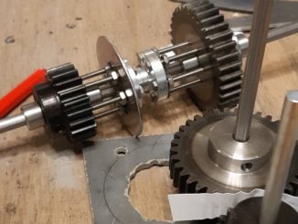
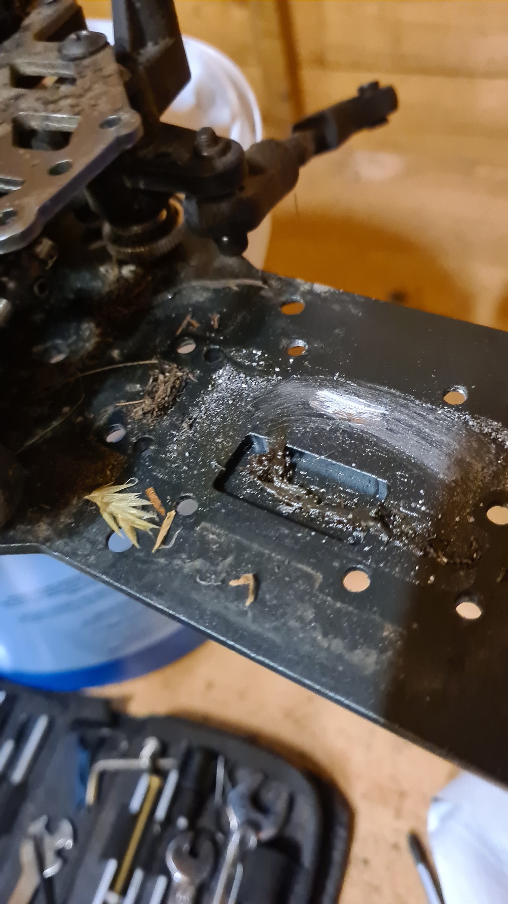
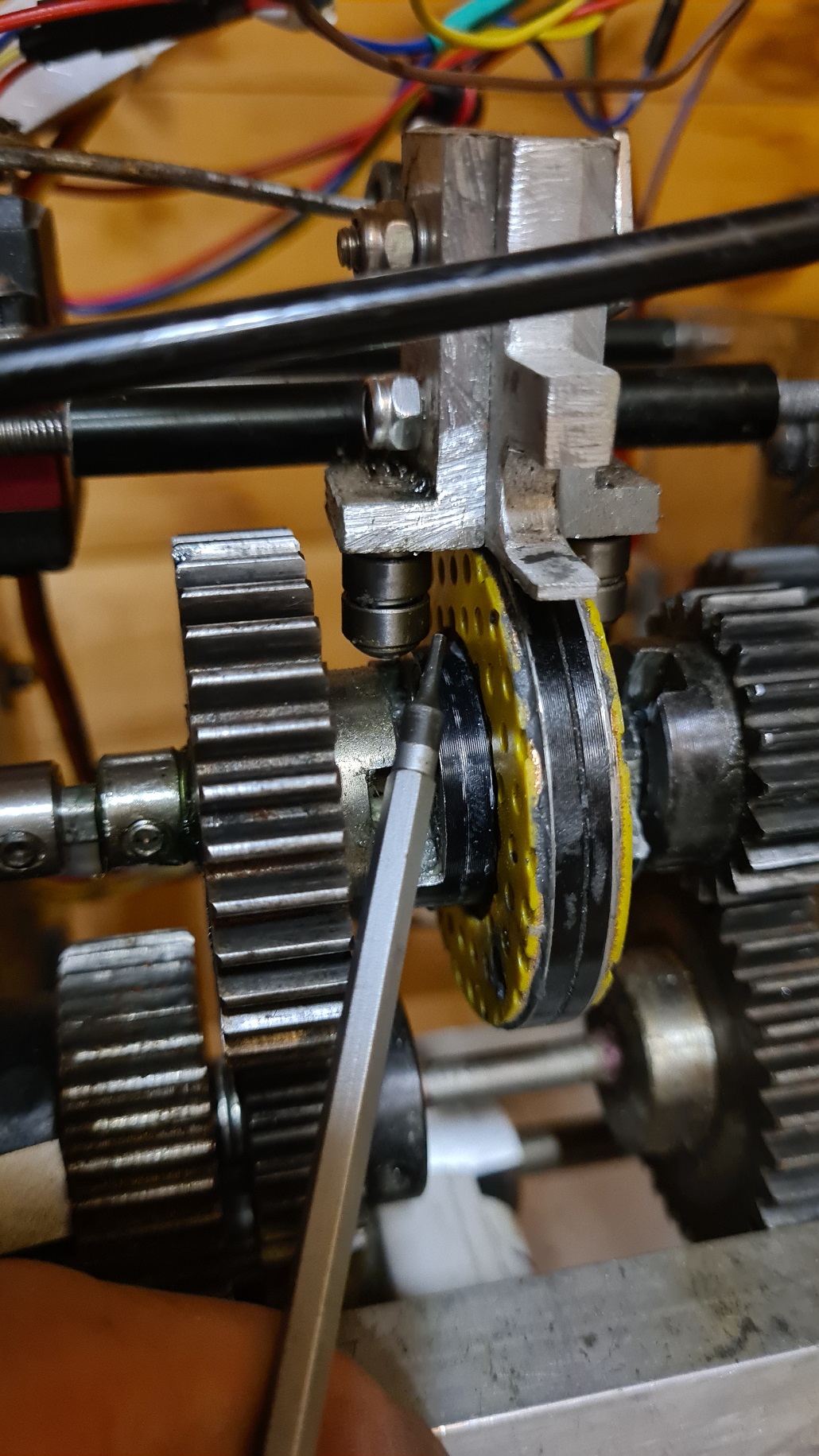
In the below you can see where one PTFE white washer has just shorn off the gear selector.
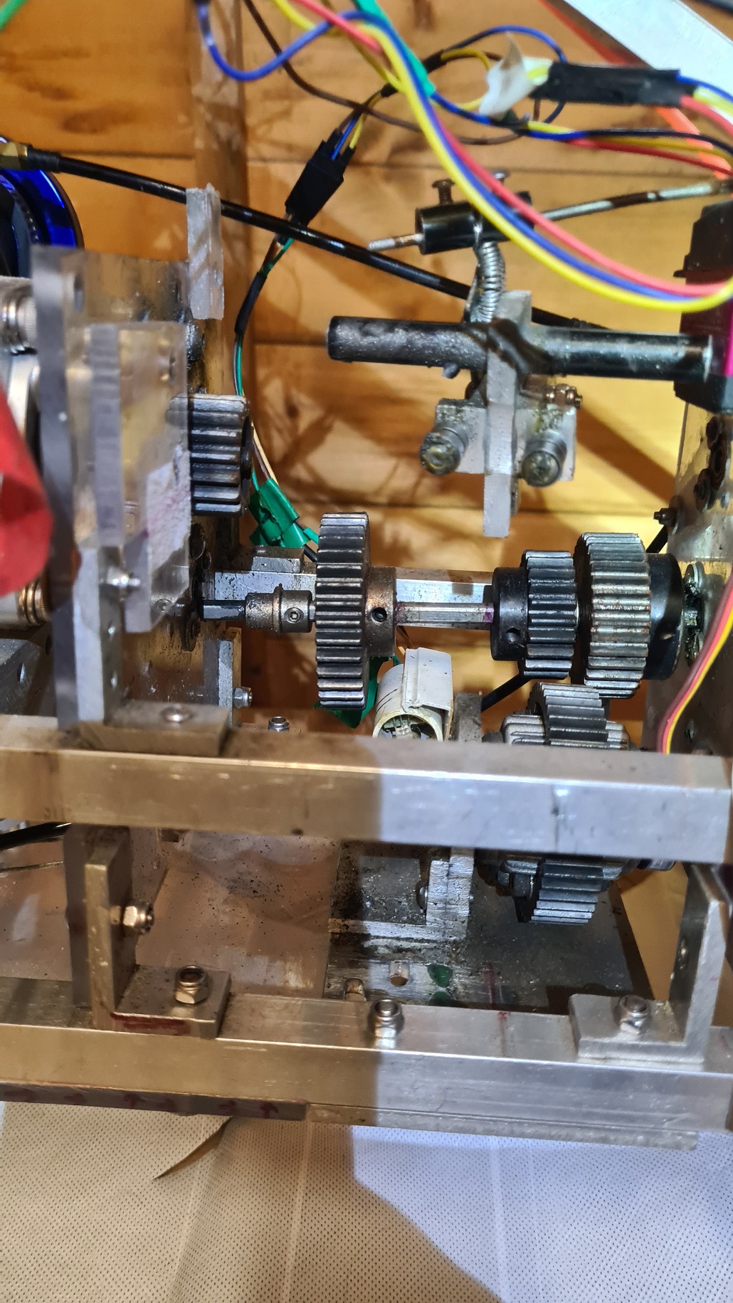
A quick reminder of the gearing – the gears to the left and right of the gear selector hub are free spinning, the gear selector rotates with the engine motion.
Slide left or right, and the dogs on the selector hub engage with the ones on the freewheeling gears and you have first and second gear.
And now the reason why I hate taking the gearbox apart.
As you can see in the above, the gearbox housing is held together with long threaded steel bars that have to come out horizontally. The holes they go through in the Perspex are precision (hah!) drilled so I can’t get them through the holes diagonally, which would be much simpler.
However, as you can see, the steel threaded bars are blocked by the rollcage.
So that will have to come off as well, which then means I have the whole upper assembly flapping in the wind. I can either disconnect every cable from the Pi to the sensors, or carefully balance the top assembly while I get the gearbox apart.
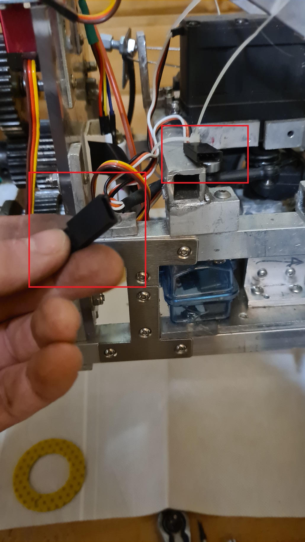
During this there is a faint click sound and the thwap of plastic hitting aluminium. Some connector has come loose, no idea what it is supposed to click back into. No matter, there is a candidate shown in the above, but I am going to have to take the entire receiver block (the clearblue box at the bottom of the chassis) out anyway to fiddle with the servo channels in any case.
An easy way to deal with the problem – chuck it on the pile of problems marked “tomorrow”.
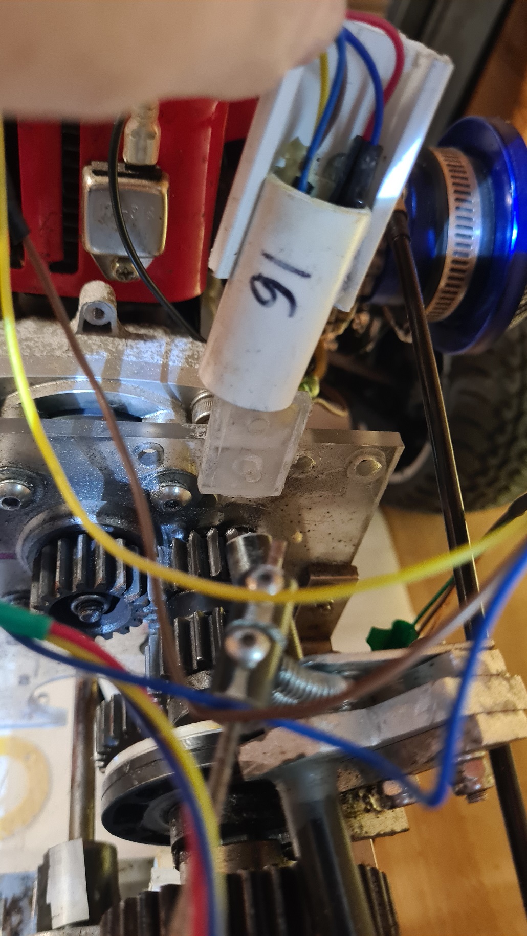
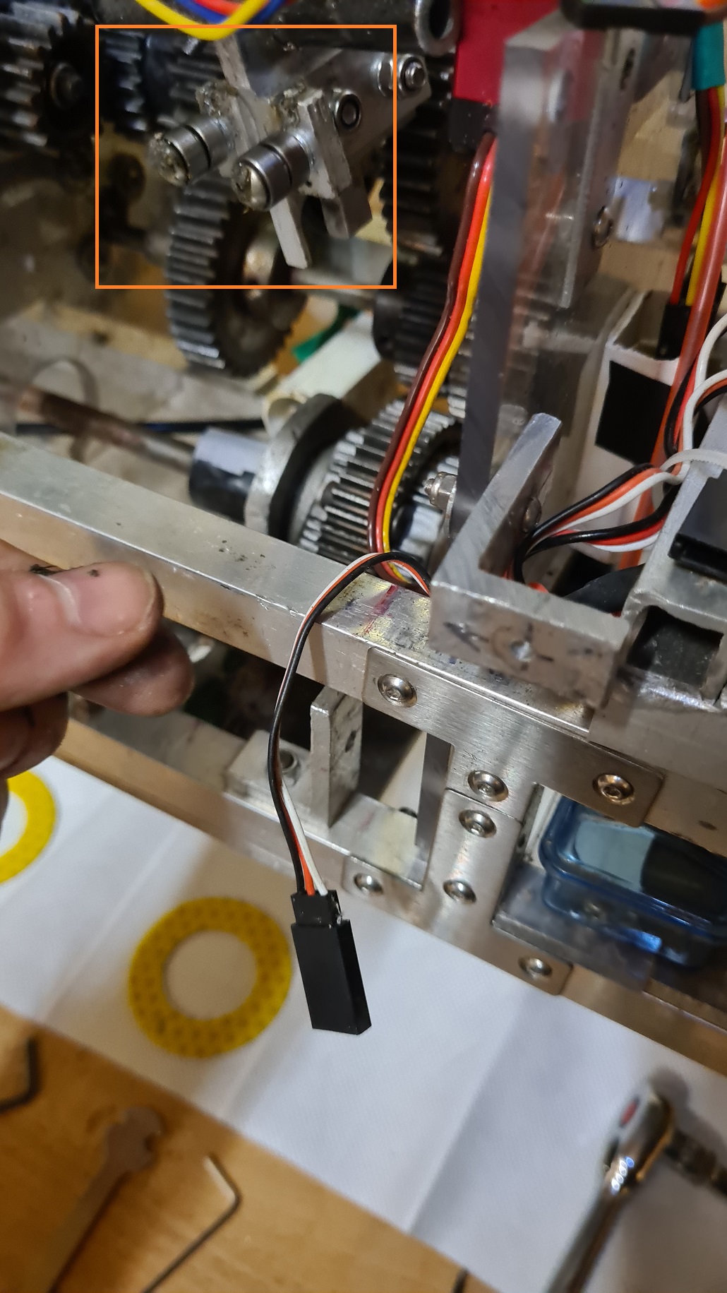
Another casualty of the disassembly, the ending RPM counter (Pi GPIO channel 16) has also come loose. On balance I would rather it came loose here in the Shed of Tools than on the Testing Field of Perpetual Disappointment, so there is that, at least.
I check the bearings and they seem to be bear-ing (heh) up!
Forty five minutes and a balancing act that would impress Olga Korbutz, I ease the main shaft free.
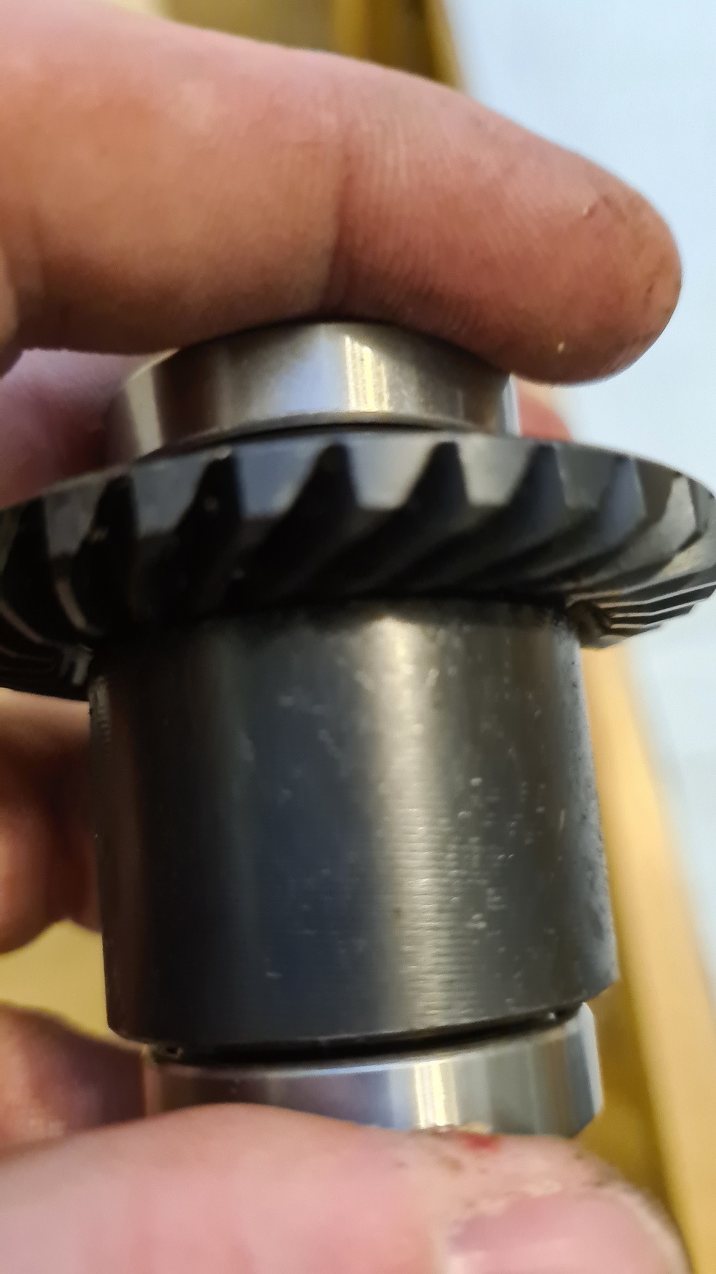
And yea verily, the glittering prize, a greasy shaft upon my workbench.
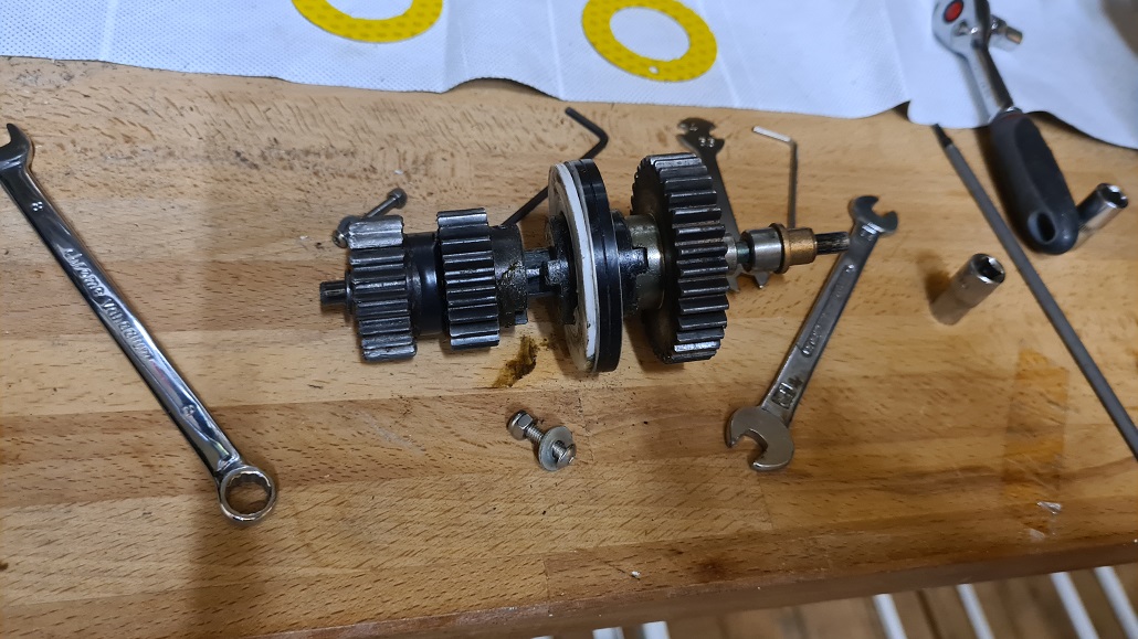
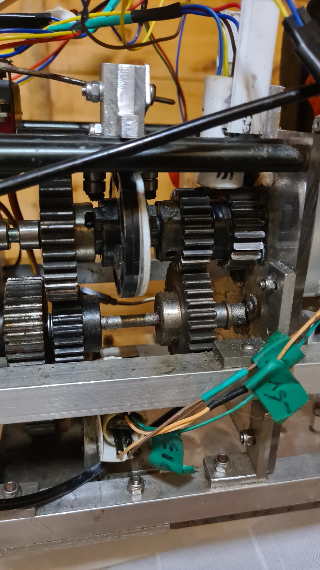
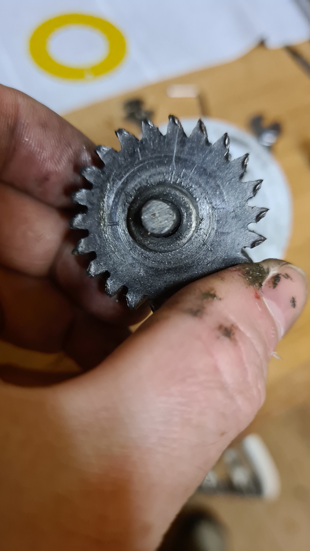
A quick shufty and it looks like the pinion gear is feeling the load a bit, but at least these are worn teeth rather than graunched as we saw on the CheatMobile.
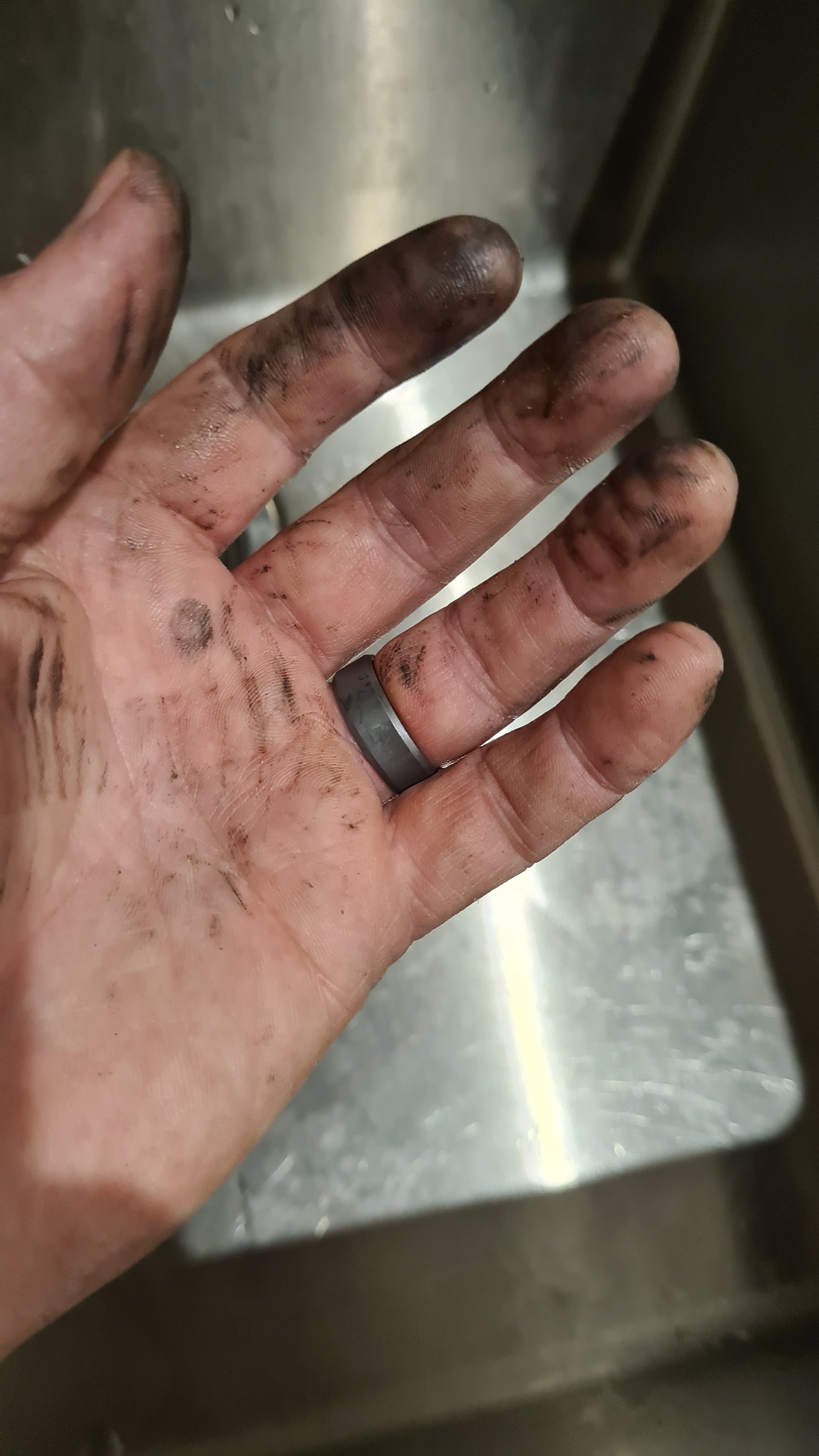
And for the haters who claim my hands are always clean – some filth at last!
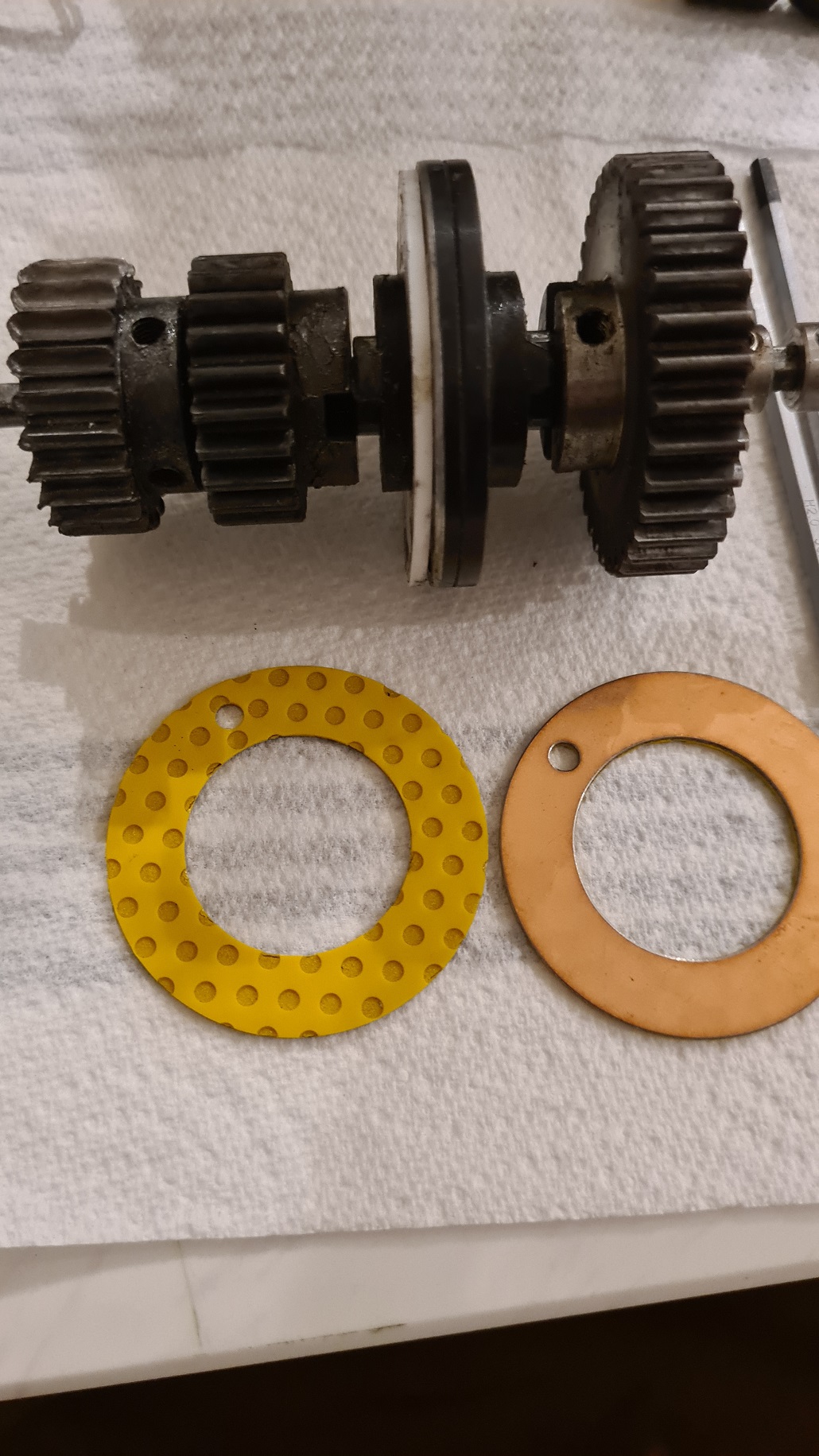
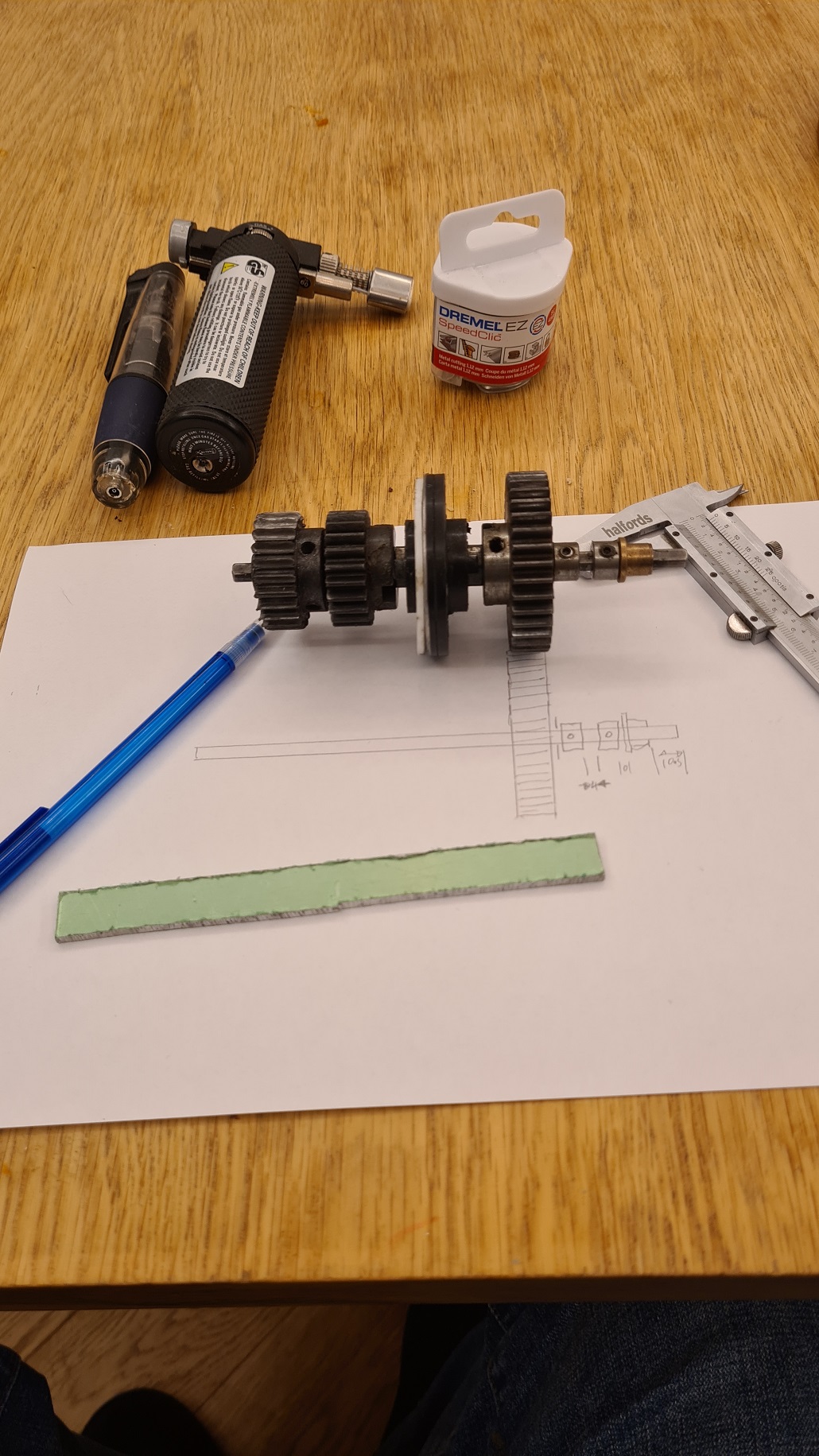
The driveshaft is now ready to have the replacement thrust washers installed. I will need to get both gears off on the left of the selector hub so the hub can be pulled free and I can access both sides to attach the shiny brass ones.
First, I am making a note of where each gearwheel sits on the axle. The lower axle goes through the read of the gearbox housing a bit further than the top axle, this is so I can fit it and it will be supported by the housing while I finagle the top axle into place. Persuaders are at the ready – acetone to dissolve the threadlock, soldering iron to warm the grubscrew and if that fails then I shall burn it with fire from the mini gas powered braising torch.
Well it actually needed the Very Big Persuasion as it turns out. No matter, I have the drive pinion off, and in a rare fit of forward planning, have a replacement gear ready to go.
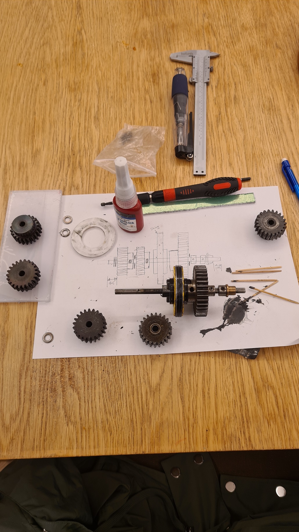
As you can see in the below, from the top – old worn out pinion, shiny new one and a scarified gear selector hub sanded free of PTFE glue and cleaned with acetone.
X
I glue the thrust washers on with JB weld and let it all dry overnight. I tried really hard to not get too much glue in the hub cutout holes as this will cause a rotational imbalance right in the middle of the shaft, which will cause the shaft to bend. But there is no way of knowing how successful I was in that, so once again it is a prayer to the eternally deaf Gods of Cnuteneering…
The thrust washers are a little thinner than the PTFE ones so the clearance is a little more generous. This is not a problem though I think.
![]()
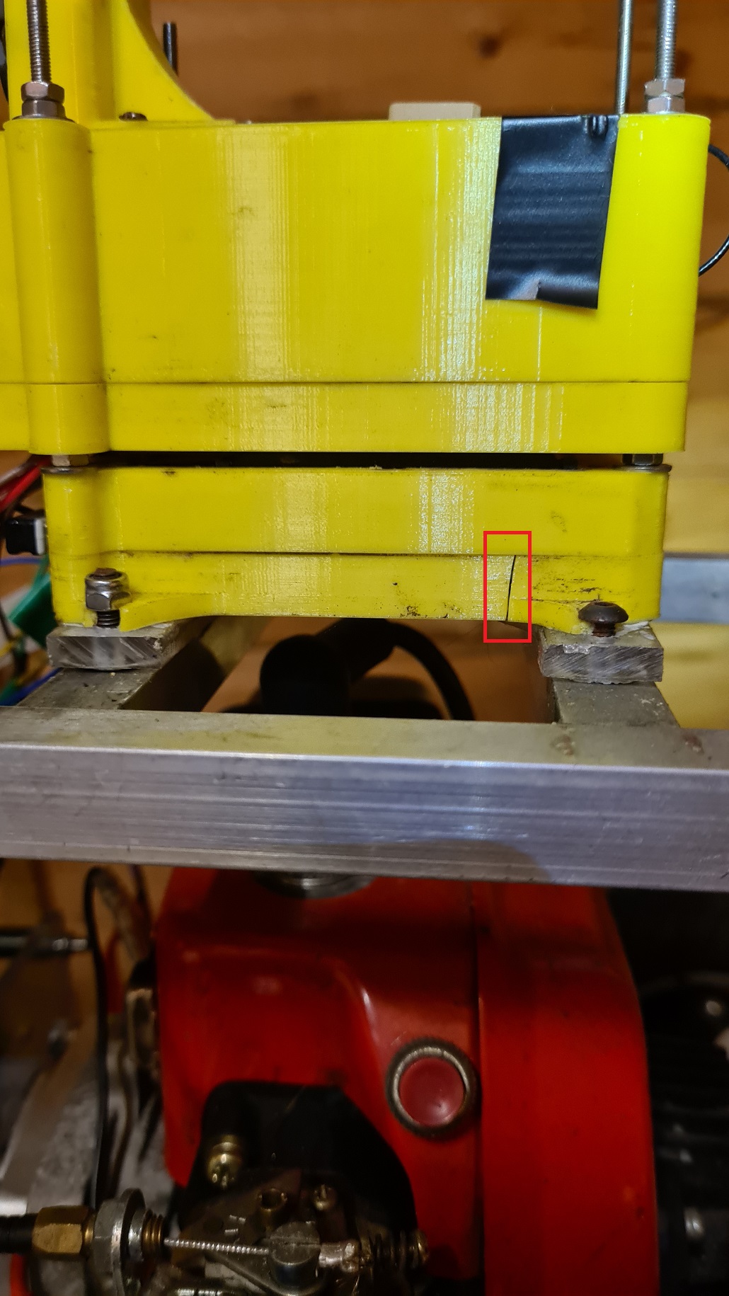
This is a problem however, the Raspberry Pi case appears to have cracked down the side. This is bad on a number of fronts, not least as it now means the case is even less waterproof. If it cracks all the way then the Pi can fall out onto the test field.
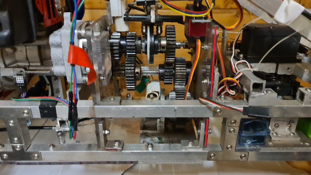
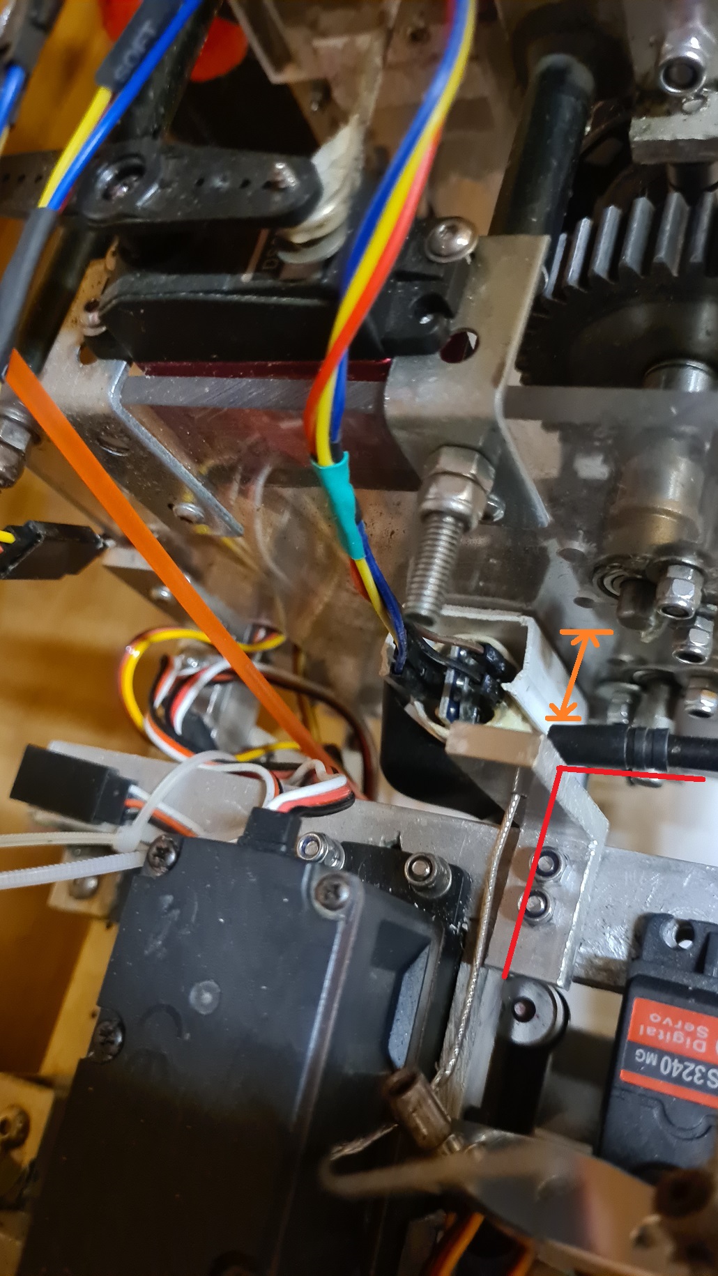
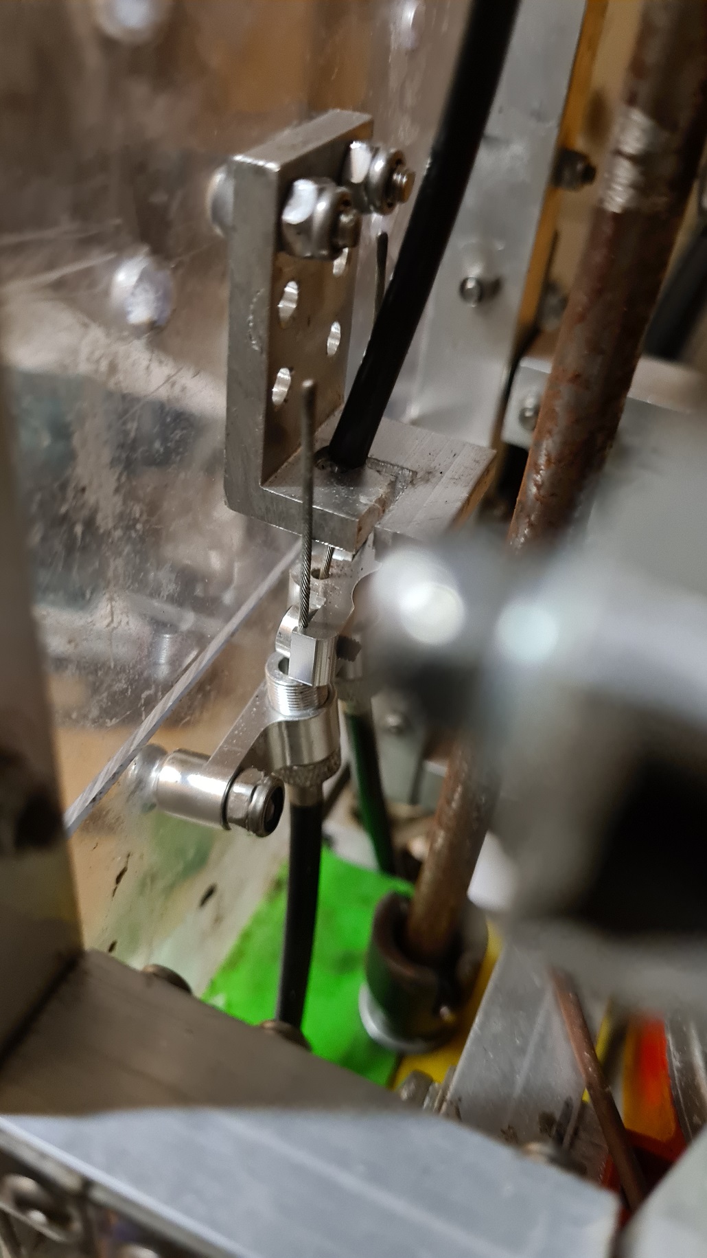
That is a problem for another day however, so I can now focus on sorting out the brake cables. Below, you can see the 90 degree angle (red lines) I have to get the cable around to get it aligned to the servo that will pull it. The gearbox housing is also quite close to the bracket (orange arrow) which could be a problem.
The brake units look like this:
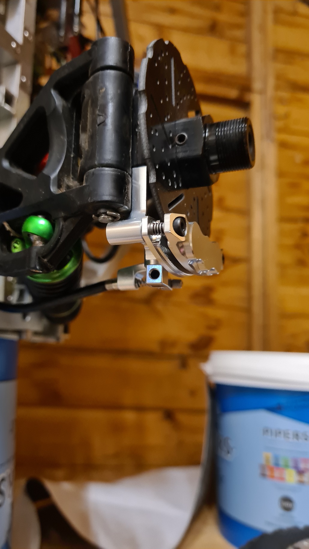
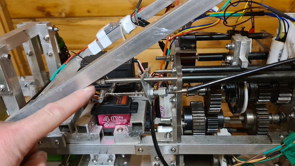
I use a 90 degree bend off a bike cable guide, and reverse the L shaped aluminium that is now holding it so there is enough space between it and the front of the gearbox housing. You can see the throttle/brake servo dangling at the top there – a 40Kg pull should be enough as the throttle/brake servo on the Cheatmobile is rated at 30Kg.
This seems to work quite nicely, there are no longer any sharp corners for the brake cable to have to bend around, as you can see in the below – brake cable is in between the red lines as it passes through the car to the saddle at the rear.

I just need to fix the brake lines to the saddle and then the brake lines are done.
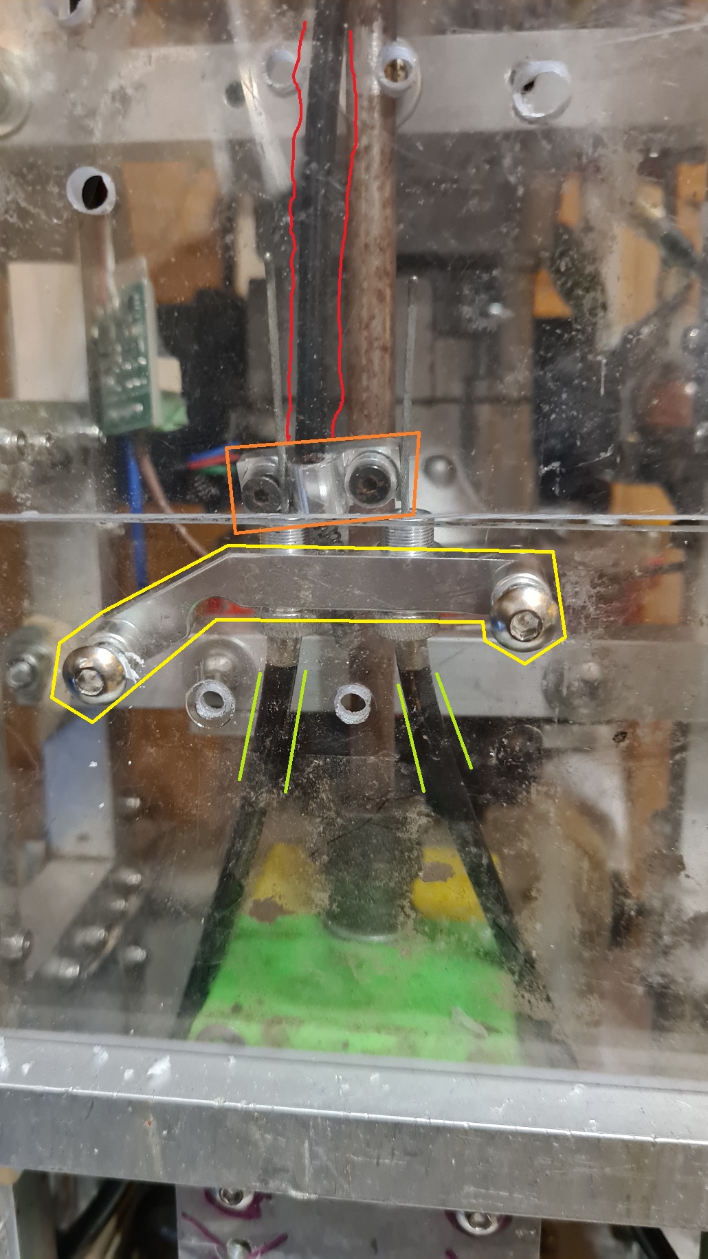
In the above, you can see the brake line that is pulled by the servo surrounded by two red lines, the saddle in the orange box that is pulled when the servo moves. The individual disc brakes (lime green lines) are attached to the saddle through a retaining mechanism, inside the yellow box. If I just take the top Perspex plate off, I can get access to the saddle to attach the cables.
In the interim I have cause to visit the British Museum with MBWK and my not so little anymore kids, NotUnicornAnymore daughter and Ammut The Devourer son.

I must have stood for quite some time marvelling at the sheer beauty of the engineering in this ceiling which places my own efforts somewhat in place.
No matter, back to the shed of light and hope only to find the Cnutmobile feels threatened and has reared up.
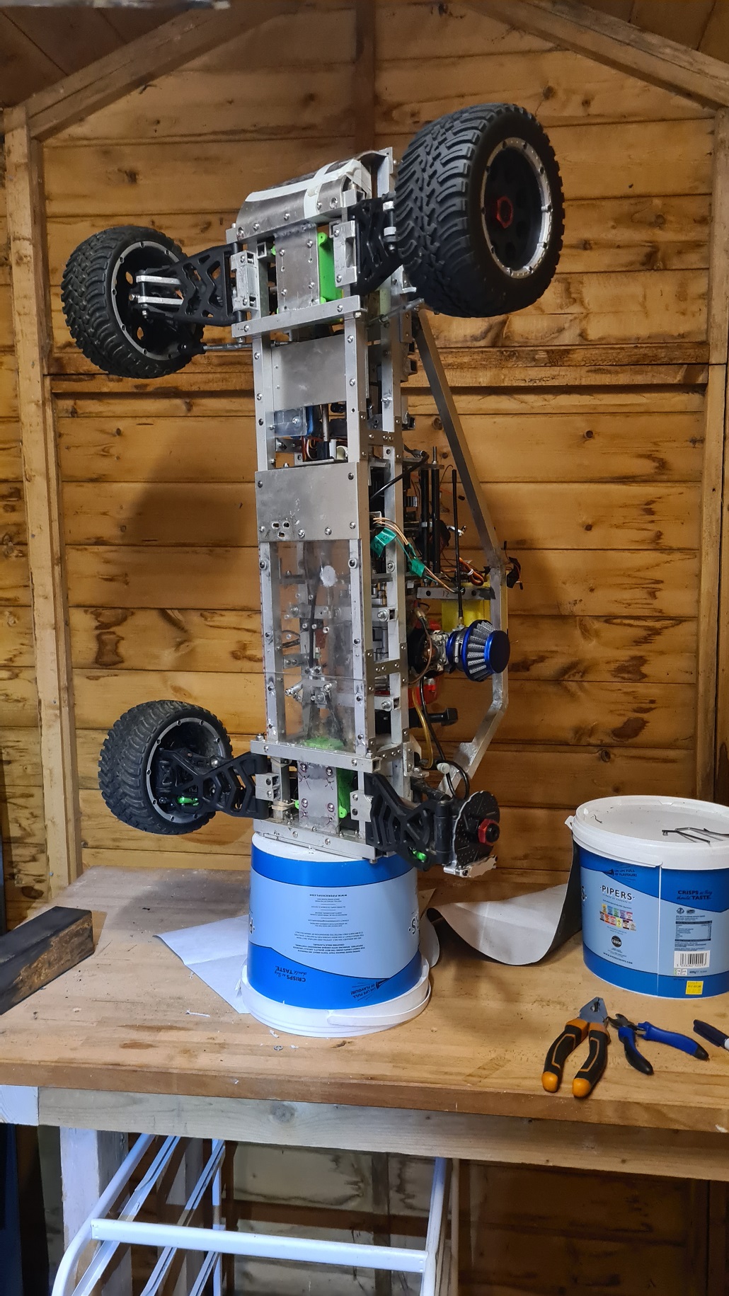
Either that or it’s mating season. Either way, I still need to brace the brake line before it goes into the saddle so that when the cable is pulled, it has something to push against. Luckily I have some angle aluminium hanging about, and there are already a couple of holes in the chassis bottom from some other mounting previously.
First up, I drill some pilot holes.
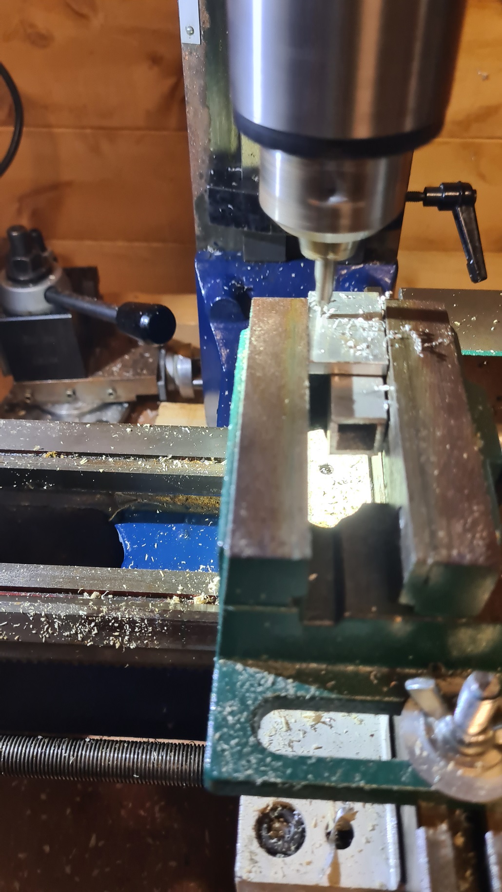
This is quite a milestone for the CHFWLMM, it is the first part for the Cnutmobile that I have machined on the milling machine so I am a little excited.
The drill bit then needs to be changed from the centre drill bit to the 4mm I need to get the bolt through.
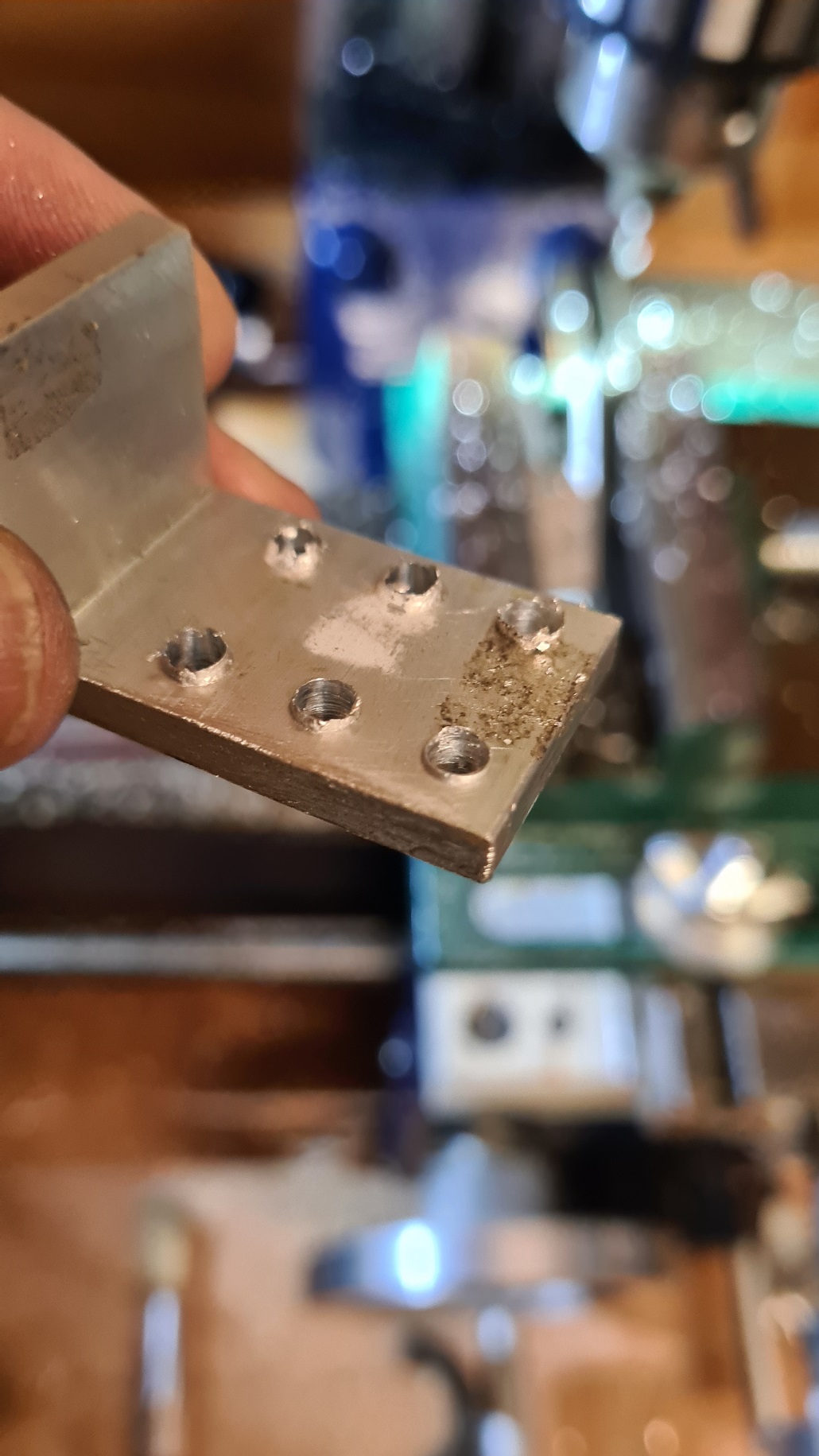
I seem to have a bit of excess material around the holes where the drill went through, not sure if I was using too low a rotation speed or downward motion there. Any ideas? No matter, can deburr it with a countersink bit.
Next up I need to cut a channel to accept the brake cable, so on with a 5mm end mill and into the material. As this is on the same side as the long bit of the L shape on the aluminium, opposite the holes in the above pic, the milling bit has to be at full extension and this is bad as it wobbles a bit. The pocket I cut is about 2.5mm deep which I am quite pleased with. Not so pleased that I had to move the pocket across a bit as the first cut was not where I wanted it. In hindsight, should have drilled a pilot hole, then a 5mm drill bit into that a short distance, then put the end mill to finish off the hole.
I also need to cut a sideways channel into the bracket, to allow the brake cable to pass in from the side. This means if I want to take the chassis plate off, I don’t need to re-thread the brake cable through the whole assembly.
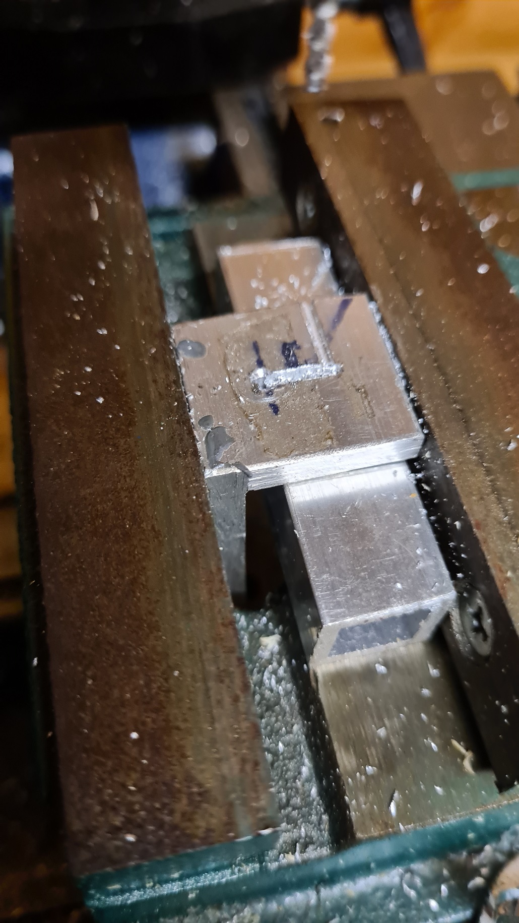
Progress was good with the 1.5mm end mill bit but impatience led me to go to far too fast and I broke the bit. Ditto for the 2mm bit as well. It was overall, quite tiresome. I did manage to get the vertical channel cut though, and could do the sideways cut with a hacksaw. Lessons will be learned, etc, and another AliExpress order coming up…
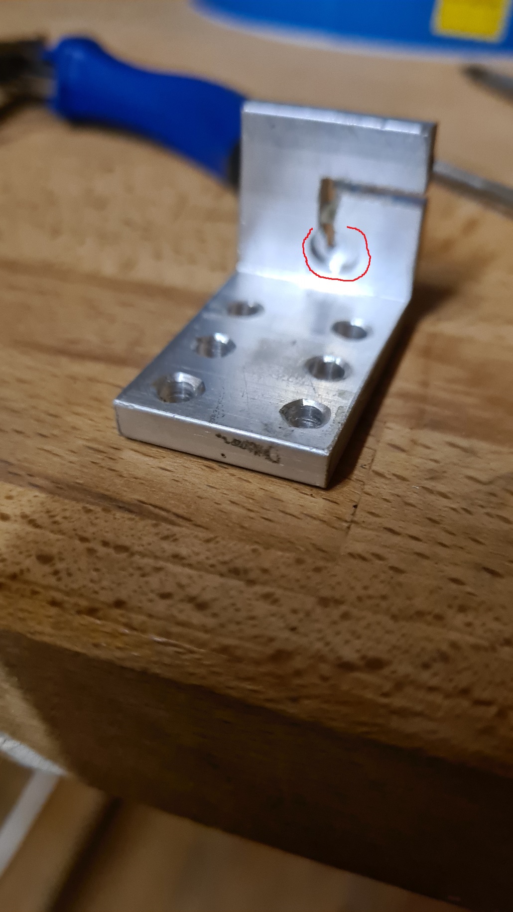
Not quite as polished as I would have liked, the pocket for the brakeline is an oval instead of a circle, but it fits and it works so that is the mainstay of Cnuteneering. I do need to sort out the vice on the mill though – I have one ready to go but as yet unfitted. The drill press mill I am using is crap, the jaws roll when meeting the work piece so it is hard to adjust it so the drill goes through the workpiece at 90 degrees.
It is fitted, if I pull the cable with some pliers then the brakes cinch. I am not sure if the servo will have enough grunt to pull the cable, but we shall see in the next instalment when I sort out all the Tx/Rx channel stuff to hopefully get it all working properly and trace where the hell the cables are coming from and should be going.
In the meantime there is always a distraction or two.
Still waiting for:
Nothing but need to order some new milling bits
Still left to do / think about
Petrol tank leak
Move gearchanger to 3 position switch on Tx
Throttle/brake servo calibrate
Switches to pi and rx power feeds
End point adjustment for servos and control mechanisms Dumbo RC setup
Body shell
Look at how Root superchargers work
Pics, vids, words and music © El Cnutador 2023