Welcome back to Cnuteneering, where the possible is made more difficult by bone headed ignorance, overenthusiasm and pointy metal things being brought together.
You may want to refresh your memory on the project in part one.
I have slightly updated the goals:
Design goals:
Fast as possible on offroad; too big to have on roads. I will set a target speed of 50mph.
4 WD.
Must be able to reverse, and brake.
Unbreakable, or as close to.
Must be able to mount GoPro or similar camera on it.
Cheap as possible.
Doing some reading, apparently 2 stroke motors do not need a battery for ignition. They have a magneto inside (little dynamo) which is fed through a rectifier / voltage hop up on the motor to generate current for a spark. This is good as I don’t have to worry about circuitry for the car, and bad as an electronic ignition would be awesomely cool.
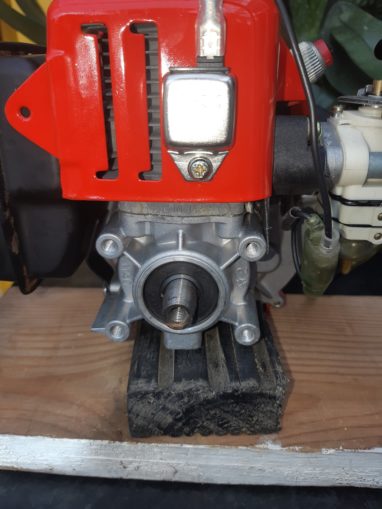
Right now I have an engine, a fuel tank and a big tank of unleaded. Plus a bottle of two stroke oil, which is to be mixed in a 1:25 ratio to the petrol, hence the mixing bottle. Four stroke engines have an oil tray that components dip into as the engine turns; two strokes need the lubrication in the fuel. As I have no chassis to bolt anything to, I had to use “that bit of wood that’ll come in handy” from the shed, and here we are – the Mk 1 Cnuteneering test mount. Turns out the 2 spigots on the engine connect to the 2 tubes on the tank – one feeds fuel into the engine and the other pushes air back into the tank. One of you puffins kindly pointed that out in the comments, had I read them.
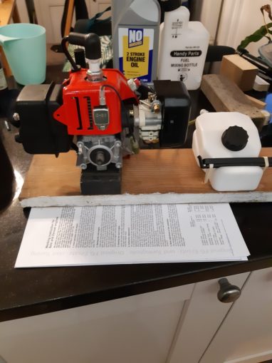
Picking the wettest coldest day I clamped the mount onto a workmate, filled it up and sent a silent prayer to the gods of two stroke motors.
Wooo hooo! I have not bought a lemon after all. And the stop button works too. Might need to work out how that operates so I can put a failsafe in to cut the engine if the car loses connection to the transmitter.
So next up is to find a clutch, clutch holder, clutch housing, bolts and all the rest of the gear to just drive a tiny 17 toothed pinion gear. And here is how I discovered why the engine so cheap… Very old design and very hard to get parts for it. At this point the “make everything yourself” idea became a bit more attractive, but this is a heavy load bearing part of the car and it needs some precision engineering.
After quite some time searching I found this clutch kit which has all the bits I need. I hope.
Next on the list is how to get the power from the engine to a gearbox, through a differential and to the front and rear wheels. Astute readers will have noted that the kit linked above does not have a pinion gear. I am going to see what sort of mount the clutch bell comes with before buying one that fits, but for now, at least, I have the clutch problem sorted.
After quite a bit of research, it turns out that gearboxes with clutches are really rather complicated in your common or garden car. They have some very clever ways of meshing gears together quietly, not least helical cut gears which make less noise when meshing than straight cut. There is also synchronisation of gears as they get selected, to minimise wear and noise.
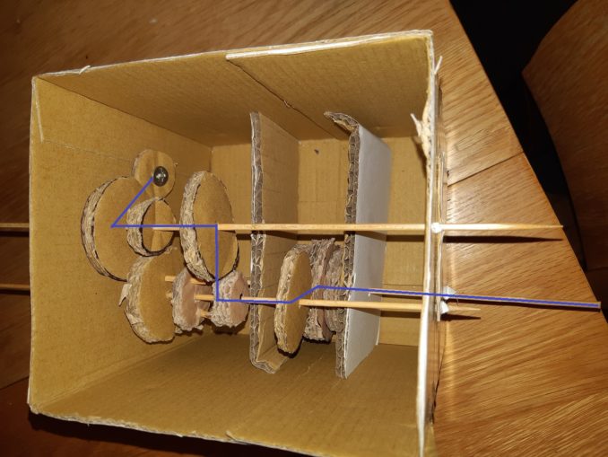
Those mechanisms are way too complicated for me to machine and really, the aggro growl of gears is quite awesome on a little car. So I am back to a basic design, done with the aid of state of the art 3d modelling techniques:
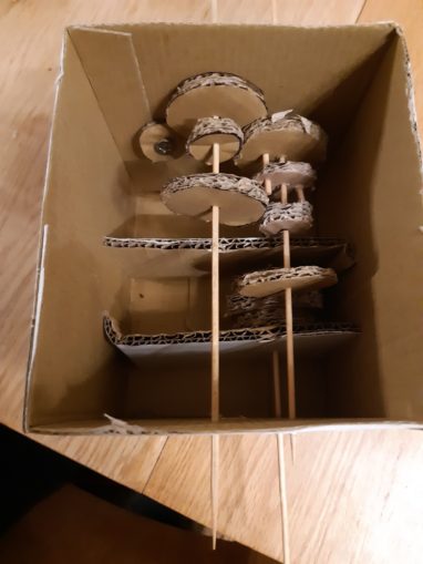
How this works is through the miracle of dogtooth gears and spline sleeves.
The gears are in constant motion and turn with the axles / shafts that carry them, except the ones highlighted in green. The dogtooth gear is free to slide up and down the shaft (ahem) to link with the gears either side of it, depending on the gear selected. When is is connected to neither gear, the car will just idle and go nowhere.
The idea is that when the car is in first gear, the dogtooth gear is pushed left into the gear by the gear selector. This forms a drive train as below:

When the dogtooth gear is pushed by the gear selector to the right, a bigger gear is engaged and second gear is now selected:
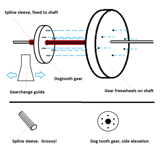
A spline sleeve is a hollow tube with parallel grooves down the length, that is attached to the shaft by little grub screws that hold it to the shaft so it turns with the shaft. Instead of having just a circular hole in the centre, the dog tooth gear has grooves that match those on the spline, so that it turns with the spline but can travel up and down the spline. On the side of the dog tooth gear are the dog teeth. My sprocker looks just fine with his gnashers as is, so I will just use bolts instead.
This is what a spline sleeve and dog tooth gears look like, and how they fit together.
I can move the gear change selector with a servo, which will be controlled by the radio transmitter.
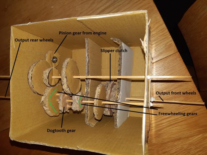
For reverse we have to add a whole load of extra bits as below:
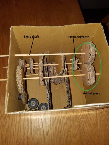
You can see I have had to add an extra shaft, another dogtooth gear, a freewheel gear for the dogtooth to drive, a gear to feed from the main engine drive shaft and a gear to reverse the rotation. Four gears and a shaft is not a good investment for a reverse gear, so I may look into having a hybrid car – a small electric motor to do reversing with. This may have the added bonus of giving me braking, as well, which is nicely efficient. I am going to have to think about that for a while.
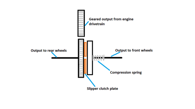
The slipper clutch is a cheap way of relieving pressure on the gear mechanism. If the front of the car goes over a rock or a bump, the wheels will not all be in contact with the ground. This will cause a mismatch in resistance in the front and rear drivetrains, and the stress of this will be borne by the gearbox, which will ultimately break.
The slipper clutch is basically a sandwich of gears and a clutch plate, squeezed together by a spring. The wheels should turn together, but if the front or back wheels are constrained the other set of wheels should still be able to turn.
Now that I have the gearbox designed as far as it works, I need to work out some ratios. In my search for clutch parts and documentation for the G2D engine, I have read conflicting reports on the RPM of the engine. Some blogs say it is 8,000, others 10,000 and even 12,000. I do not have any way of measuring the max RPM of the engine so I will simply guess and say it is 10,000 RPM,nicely in the middle.
If I want a top speed of 50MPH then I will have to do some maths to work out the gear ratios from engine to wheels.
50mph is about 80 KPH, which is 80,000 metres per hour. So in one minute, the car will travel just over 1333 metres if it is going 50mph.
The wheel RPM is therefore
r = 1333/c
where r is the RPM of the wheel and c is the circumference of the wheel in metres.
So the size of the wheel must be known before I can work on gear ratios. RC wheels are sold as just the radius and width of the wheel hub only, not the exterior tyre size.
Which is a neat way to end this instalment, I am awaiting on goods from Chy-na so I can measure the circumference of the tyres and proceed. This will be 20-40 days from now.
All pictures, videos and text © El Cnutador, Going Postal 2020
The Goodnight Vienna Audio file