Welcome back to Cnuteneering, where the possible is made more difficult by bone headed ignorance, overenthusiasm and pointy metal things being brought together.
You may want to refresh your memory on the project in:
Design goals:
Fast as possible on offroad; too big to have on roads. I will set a target speed of 50mph.
4 WD.
Must be able to reverse, and brake.
Unbreakable, or as close to.
Must be able to mount GoPro or similar camera on it.
Cheap as possible.
We left the last episode of Cnuteneering at getting to grips with the front end, which is mostly Very Busy With Stuff Moving About. And that is exactly how the previous episode started as well, sorting out the front end to get the front shock absorbers and shock tower in place. There was also some progress on getting the first custom made drive shaft built, and here is the first of these beasties.
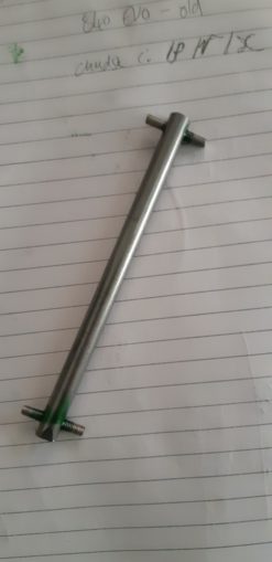
I am still not sure if I should try to harden the steel in any way and unusually no puffin came forward with any advice so for now I shall run with what I have. This is going to be an exciting moment in the history of the Cnutmobile as I will finally get the power from the central diff one step closer to the wheels.
As this is steel, I uprated my taps.
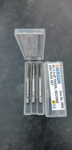
These are better taps than the ones I have at the minute as they come in 3 styles – taper, second and plug. While that may sound like the descriptions for a #FF “aid”, they are really just used to put a light thread in first using the taper tap, a deeper thread with the “second” and then finally a full depth thread with the “plug” version. So a bit more faff, but steel is a fair bit harder than aluminium and my M3 / M4 taps are looking a little worn already. Spreading the amount of material removed is easier on the tool, my hands and the work piece itself.
Now on to the shock fork itself. I am having to build these because GQ made me the drive shaft for the front wheel is right in the way of where the shock needs to go through the lower suspension arm. I have ruled out moving the shock mounting to the rear of the suspension arm as there is no way to do it without messing with the steering rods, and at the front the angles of the upper suspension arm are all totally wrong and the shock mount would have to be a long way away from the centre of the suspension arms, which would twist the arm when the wheel bounces.
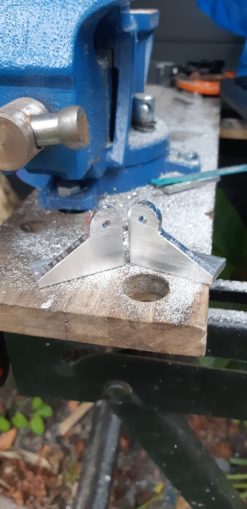
And so here begins the tale of the front shock fork construction.
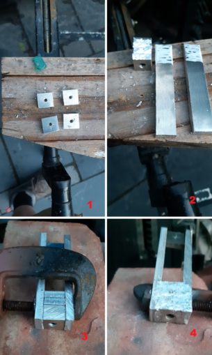
In the first pic, top left, I cut some 16mm squares and put an 3mm hole in the centre. I can then use an M3 bolt to hold them together, which you can almost see in pic 2. The squares are all 6mm in depth, so in total they are 24mm deep. Which is not handy at all because I only have M3 bolts up to 25mm and 1mm is not enough to get the nut attached to the bolt. I drill a countersink hole so that the bolt can go through far enough for me to get a nut on to the end of the bolt to hold it all together.
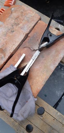
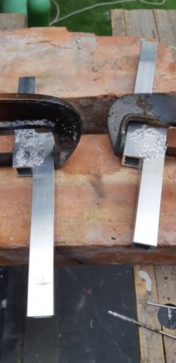
In Pic 2 above, all surfaces are nicely abraded and cleaned and ready to be clamped as in Pic 3. I braze this side, then turn the piece over as in Pic 4 to braze the other side as well.
Repeat again for the other shock fork.
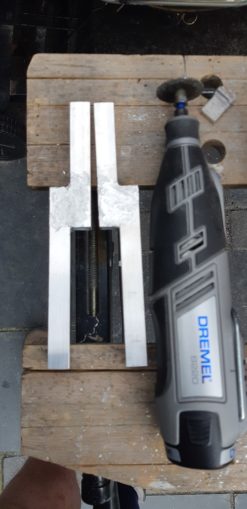
I clean them up a little with my handy Dremel ™ and try to get the bolt out
The bolt is stuck. I strip the bolt head, and try to push it out with a punch but the punch slips on the bolt shaft.
Drastic measures are required, I try to push the bolt out by clamping in a vice.
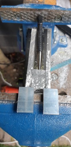
It eventually pops free and I can get some pliers on the head to pull it out properly.

Looks like some solder had dripped in and melted to the bolt, which was bad while I was trying to get it out but pretty good as I know I am heating the block hot enough so that the solder is melting all the way in to the middle.
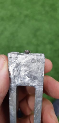
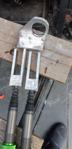
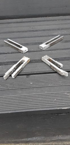
Now all cleaned up and ready to go, the ends of the blocks have their holes tapped at M5 with a wider hole as closer to the surface. This was a pain in the backside to get done – I drilled out the M3 with and M4, then M5 drill. Taping an M6 drill to exactly 11mm so that the suspension shaft had space to be in, drilling 11mm deep, then M7, then M8. This is because I want the 8mm shock shaft to go into the block a little further than the M6 thread will allow. And yes, I did measure not twice but 3 times just to get the wider hole depth just so.
I got there in the end, and fettled the central diff piece down a little so the electric motor can be mounted next to it.
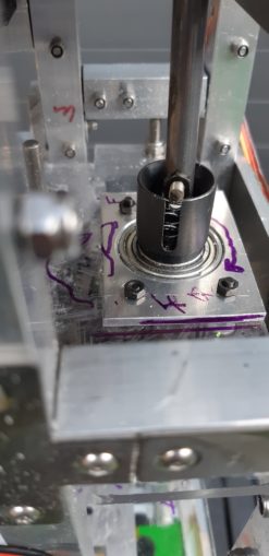
Fitting the forks to the car should be simple, it is just a couple of holes in the fork tines to let the mount screw through but yet again the fuckup fairy comes visiting:
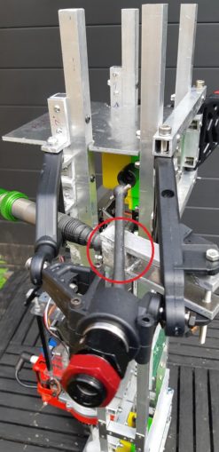
In the pic above, in the red circle, you can see the driveshaft going through the fork block. Fucksticks!
The long shafts are 16mm wide and 90mm long which is the distance from the mount point to the driveshaft top side. At this point, I should have added the extra 24mm of the block that is bolted together, but I didn’t. Because I am a stupid Cnut.
My sheets of 6mm aluminium are 150mm long, and I used the remainder of the fork to cut for the 16mm squares. I remember briefly thinking – perhaps I should just leave them as this length and cut them down later, but the allure of an easy piece of 16mm wide aluminium was too strong.
Bear in mind that the 6mm aluminium is too big to fit on to my angle grinder jig, and so these have to be cut by hand. Every single tine on the fork takes 12-13 minutes to cut by hand, plus a little draw filing after to take the edges off. Cutting and roughly finishing 4 of these tines took an hour, and when you factor in the squares, I had to cut just over a metre of 6mm aluminium plate, by hand.
Never mind, I thought – I can easily just extend the forks a little by brazing a thin plate down one side.
And here we have it –
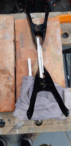
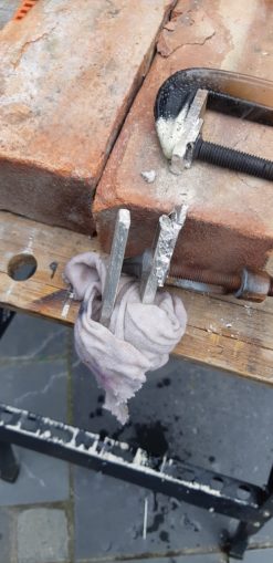
Fearful of melting the solder at the block, I thoroughly wet a rag and placed it over the block and I was ready to go.
Predictably, fabulous disaster:
The clamp went through 9mm of aluminium!
No matter, there is always the other fork to try to fix…
Or not. Gravity and the G clamp pulled the aluminium strip in half.
This was becoming quite tiresome so instead of persisting, I bit the bullet, threw away about 6 hours of Cnuteneering and just rebuilt them. I think the mismatch between 6mm and 3mm aluminium was too much – the 3mm plate was heating faster then the 6mm.
Needless to say this did not improve my mood; essentially a whole day of effort pissed up the wall for no good end. My imaginary Gantt chart now has 2 days out of schedule (one wasted day with nothing useful at the end of it, a day taken re-doing it properly.
Such is the way of the Cnuteneer. On the plus side, after another 116cm of sawing 6mm aluminium, my right arm is *pumped*. Making the replacements was a bit quicker as I know now what works best when building this piece.
That is largely the suspension arm problem sorted I think; still need to build a shocktower though.
For now, getting the central gears all sorted will also be a useful thing to do. I need to move the central diff just a little closer to the next gear which is hard as the hole that the diff goes through is right in the gearbox. I either take the whole car apart to get the plate off, file the hole which will take forever as I can move a file about 1” in a stroke, or find another solution.
Aaaah, Dremel to the rescue:
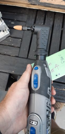
An attachment that rotates the head by 90 degrees. I can now get in to do what I need to.
I can also fit a reinforcement plate as the epoxy is looking a bit tired:
This being Cnuteneering though, there is always something that goes wrong:
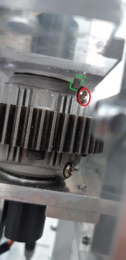
The retaining bolt (in green box) is going to bang in to one of the central diff bolts (in red oval). FFS.
Some rejigging and at last, the plate is installed:
I can just about get to the bolt heads with a small allen key wrench now that I have made them come through the plate from the other direction.
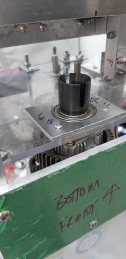
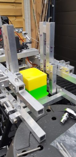
Now to crack on and get the electric motor mounted:
This is loosely held in place by gravity. I have already fettled the big aluminium O to give space for the motor.
Measuring how far the mounting plate needs to be from the chassis is a bit tricky though; I can’t get a tape or a gauge in there to accurately measure.
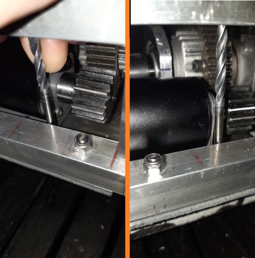
So I put drill bits in there as feeler gauges until I get the right size.
I can now cut some holes in the marked out bottom plate
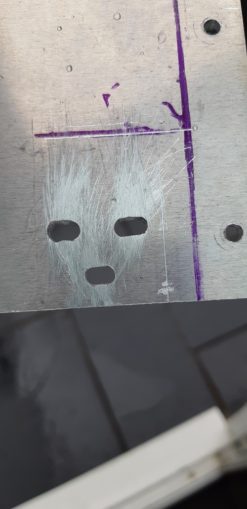
The holes are oval so I can move the motor sideways a little to adjust it so it gets to bind to the central diff /just so/.
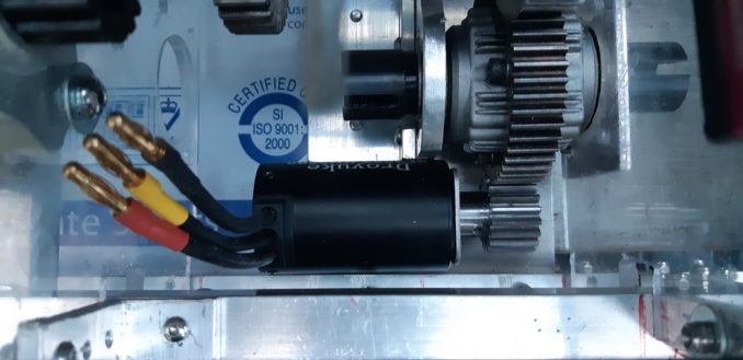
Getting a bit tubby though, this is another half kilo to add to the weight of the car:
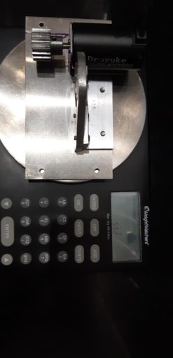
That is pretty much the central gearing sorted now, I have made the central diff bind better to the drive gear and can now mount the electric motor to it.
I can fit the drive shaft to the car now, but it is a little too small on the central diff end. I fill the end out with some nuts:
And then pad it each side with a couple of springs (200) to keep it nice and central.
At this point I realise that the wheels will turn in reverse when a forward drive is exerted through the front central driveshaft. I disassemble everything, again, and turn the diff gear over in the diff gearbox so the rotation is the correct way.
I am too tired and sick of it at the minute to take much joy from this minor victory; the failure with the suspension forks is still weighing upon me I fear. But, the drive train is now complete and coherent from the engine to the front diff box so that is quite good I suppose.
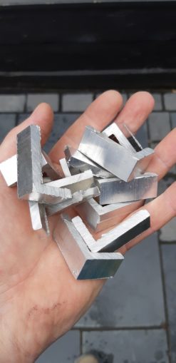
Retreating to my comfort zone of mindless powertoolage, I know I will need a whole load of angle brackets. So I cheer myself up by cutting what I know I need plus half again. I still have a metre and a half of angle aluminium left and the grinder stand takes a good 10-15 mins to set up to get it trued and level so everything is at 90 degrees or perfectly(ish) flat.
A half hour of thoroughly satisfying grinding and I have a pile of useful bits.
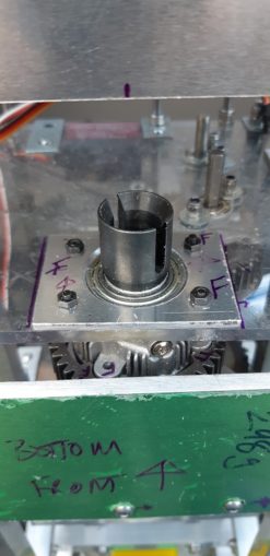
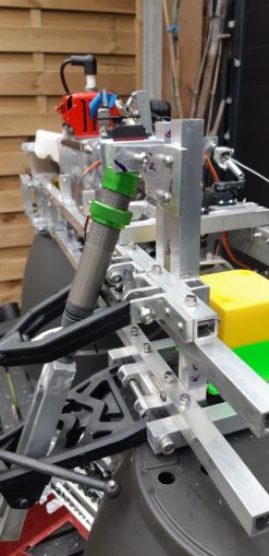
And now the bit I’ve been putting off for a while as I just don’t know what it will look like, how to attach the shocks to the suspension arms. Most of my cars have a shock tower plate at the front, and this is kind of what I have been aimlessly wandering towards. But the front diff gearbox is right in the way, and are a lot of bolts / nuts too.
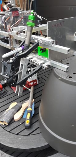
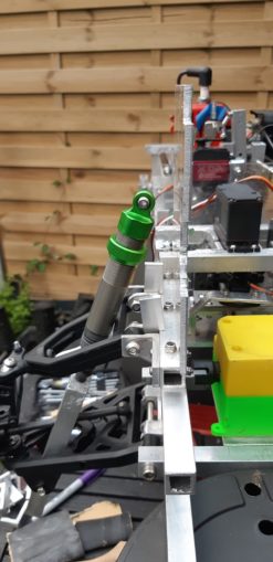
I mount the shock absorber where I think it should go by drilling a hole in the forks. I am _very_ careful to avoid cutting it too short just yet, so the overhang will stay until the wheels are on I think, it will be just 2 bolts to remove to take the assembly off and cut it to the correct size. The Sharpie pen is to balance the shock in a mostly upright position so I can take a photo.
Perhaps a sideways facing plate might do the job?
I can fix this to the top and bottom chassis, but the plate I have is just a little too short.
The plate just won’t reach the top of the shock and the bottom chassis rectangle.
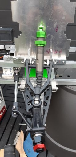
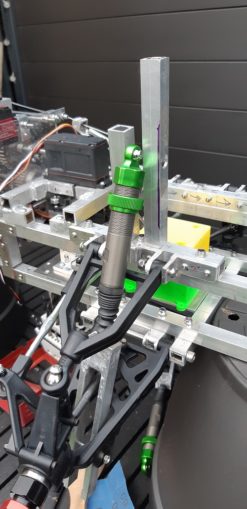
So I go for plan B, some box section uprights that I can make long enough to attach to both bottom and top chassis rectangles. I can put a bit of angle aluminium on the uprights to pass a bolt through and pick up the eyelet on the top of the shock.
This being Cnuteneering though there is always a snag. If I have the uprights close enough together then the drive cup from the front diff gearbox is in the way.
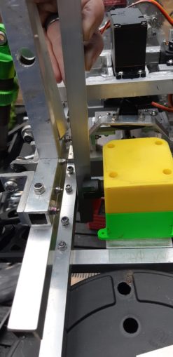
So, I need to get a dogleg bit of box section, and I warily fire up the brazing torch.
A bit of application of the trusty Dremel, and they look pretty good if I say so myself. They pass the battery of high tech fit for purpose checks I have instigated on my brazes, “drop them on the stone patio” test and the “can I pull them apart with my bare hands” test with flying colours. Ah, success, that long forgotten feeling.
Some drilling (well quite a lot actually, 2mm pilot hole, 3mm then 4mm holes after) and they now fit quite nicely to the top and bottom chassis components.
Some actual fettling to get the suspension mounts looking spanky, and I have started enjoying the project again. That aluminium powder is from a manual hacksaw only, which might give you some understanding of just how much sawing there has been of late. My soft office workers hands have gone quite tender and puffy, and my grip is not as strong as it was as a result of the sawing, filing and faffing up to now. Must man up and lay off the soy I think.
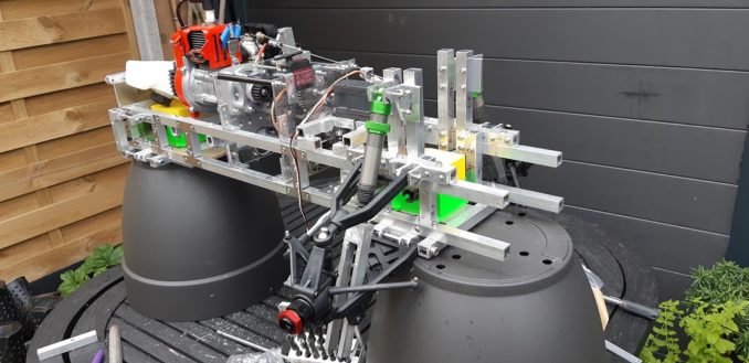
I can fit one side now and it looks good I think, whether it will be strong enough who knows?
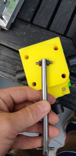
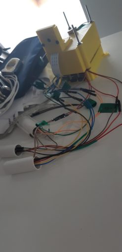
As things are turning my way for a change, I am laying off putting the cross piece in just yet. I still do not have a mounting place for the PiTelemetry (must get a better name for that component!). As a reminder here it is so please give it a better name than “the Pi thing”. Kraken like level of cables to manage, too.
I am thinking that the crosspiece that will hold the shock tower uprights together could be a goer, perhaps bolt the pi thing on to a bit of polycarbonate and then have that clip in a removeable fashion to the crosspiece might work. I will still need some way to mount it so I can video the gearbox in operation though, but that is something I will put on the respectably diminished THTTARN pile.
Still waiting for:
3mm drill bit that I broke doing the shock tower build.
Still left to do / think about
End point adjustment for servos and control mechanisms Dumbo RC setup
Siting of RPM counters
Siting of battery and control gear
Fit the front plate; do I bend the front of the chassis up or not?
Rear central driveshaft
Differential gearbox to wheel dogbone driveshafts
Design and fit rollcage with picam mounting
Pics, vids, words and music © El Cnutador 2021
The Goodnight Vienna Audio file