
Welcome back to Cnuteneering, where the possible is made more difficult by bone headed ignorance, overenthusiasm and pointy metal things being brought together.
You may want to refresh your memory on the project in:
Part One.
Part Two.
Part Three.
Part Four.
Part Five.
Part Six.
Part Seven.
Part Eight.
Part Nine.
Part Ten.
Part Eleven.
Part Twelvety.
Part Thirteen.
Part Fourteen.
Part Fifteen.
Design goals:
Fast as possible on offroad; too big to have on roads. I will set a target speed of 50mph.
4 WD.
Must be able to reverse, and brake.
Unbreakable, or as close to.
Must be able to mount GoPro or similar camera on it.
Cheap as possible.
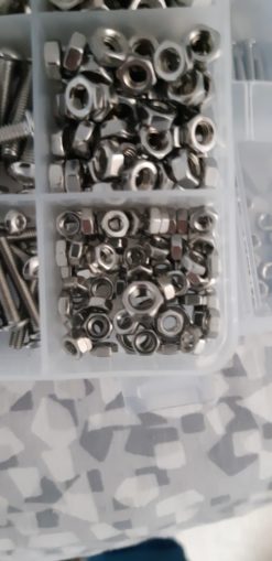
We left the last episode of Cnuteneering at the building of the mobile Pi camera unit with GPS, and the completion of the differential gearboxes. In the meantime the 3mm studding has arrived so I cut that up into the right sizes, drilled and tapped where needful and could get cracking on fitting the sensors to the breadboard so I could close the Pi and breadboard cases up in their final positions together.
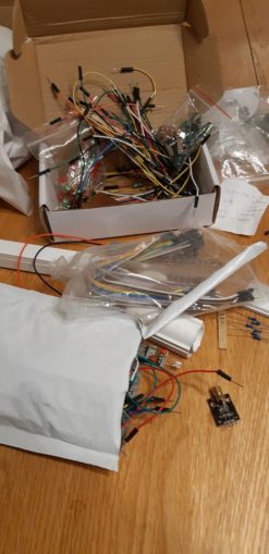
What looked like a lot of cables wasn’t, really. What I need is some length cables to extend out to the site of the sensors. The laser LEDs need +5V and GND, the laser sensor and temperature probe need that too plus a signal cable.
All in all it is a bloody mess.
The sooner I can put everything together the better!
The temperature sensor needs something called a pull up resistor which bridges between the +5v and signal cable. There seems to be some debate online as to whether it should be a 10K Ohm or a 4K7 Ohm resistor used here, but these are all at 3.3v and this unit is 5v. One further issue is that I have 1K, 330 and 10K Ohm resistors… But no 4K7.
Trying to scrutinise a resistor is hard going when your eyesight is as poor as mine; repurposing this resistor I have no idea what the colour bands actually are. Is that black or brown?
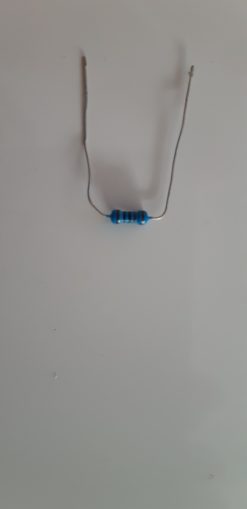
Luckily my handy AVO meter told me it was a 330. Chaining a couple of these and a few 1K resistors I got to 4.66K Ohms in a mess of cables, just to get things moving along for now.
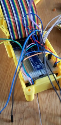
Everything is now plugged in and I can put it all together. I ran out of red and black cable for the +5 and GND cables so there is some tagging with insulating tape on the cables instead. Luckily I can buy from UK suppliers to get some more cables, but in truth, can I be arsed to go back and rewire just for a /colour scheme/?
I resolve to rewire only if I have good reason to take the unit apart.
During this I discovered this horror:
Now, the idea is that the laser is pointing at a gear wheel or a drive shaft that is non reflective with a single piece of reflective material on it. Facing the same way, the receiver will only get the light on it when it is reflected back. For this I will need some careful aim and a way to hold the components together.
I could design one and get it 3d printed but I have no idea how sensitive to the angle the sensor is going to be so maximum flexibility is required.
The PCBs that the laser and sensor come on are just too wide to slide diagonally into 15mm box section plastic conduit, and too deep to fit flat in 25mm wide plastic conduit.
Kicking about my Shed Of Powah is some 25mm round plastic conduit though, so that will do nicely for now.
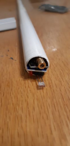
With a bit of a plastic milk carton superglued to the back of one of the lasers, to stop it from shorting to the sensor, they can both be fitted snugly into the plastic conduit. But a round tube is going to be hard to affix to the gearbox so this is filed under “Too Hard To Think About Right Now” and left to percolate overnight.
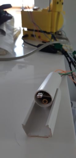
In the morning when tidying up, the answer became clear – the 25mm conduit has a sticky back that can be attached to the gearbox side and the round conduit clips nicely in place.
This will allow me to move the sensor closer or further away from the gear I am measuring, and even better when I am not capturing data with the Pi, I can remove all of the video and telemetry parts easily. Result!
So now I just had to snag some code off the internet and make it work. The temperature sensor makes use of something called OneWire technology which is a clever way of chaining multiple devices to a single signal line. Each then appears in the file system and can be read from as a stream of characters.
After a day of buggering about with the code to no avail, I was just about to give in and get a new temp sensor thinking this one was faulty, when I realised that I had the +5v and signals the wrong way round, it was an “S” on the pinout not a “5”. At least it did not burn the unit out, anyway.
This meant the Pi recognised the unit and it could be read from. Although the calibration is a bit off: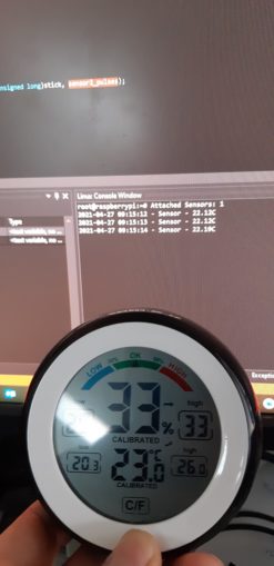
There now followed some more coding and the RPM counter is working too. I am going to have to work out just how far from the reflective surface I need to be, superglue the sensor / laser in place and then hope that I have the angles right. Just a bit of code to integrate into the main video capture program and the telemetry unit is done!
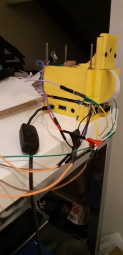
And back to real world proper Cnuteneering – not being able to find a small amount of hex piping, I had a brainwave and bought a couple of 7mm hex sockets. They have a 1/2 inch socket the other side, and will widen my differentials so that the driveshafts meet them just where the suspension arms are hinged. This will mean that the top and bottom suspension arms and the driveshafts stay more or less parallel as the suspension bounces.
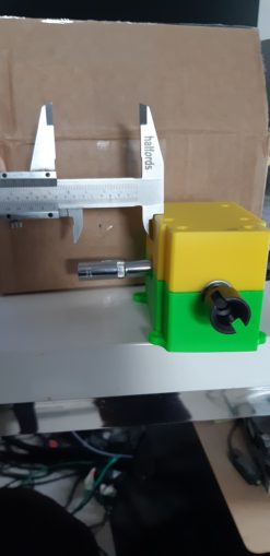
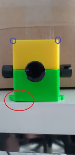
Some bad news though, looks like one of the diff case mounts has warped. No idea if it was like that when it came off the 3d printer or if it bent during storage but a small washer underneath will sort it out and the bit I am interested in – where it grips the diff gears – seems OK. The blue circles show how pointy the corners are and are where I hurted my soft office workers hands.
And that brings us neatly to the close of this episode of Cnuteneering.
Still waiting for:
Grease: Ordered 3 received 1. The other two are hopefully on the way, but you never know…
Heat conductive glue to stick the temperature sensor onto the engine.
Still left to do / think about
Cut down hex tube rider to the correct, smaller size
Rebuild the gearbox (again) but with lock nuts and threadlock
Go through the rear end design again so that the shocks and rear suspension arms are properly sited. This means I can finally attach the engine to the chassis
Sort out the car underside – at the minute it is just a gaping void
End point adjustment for servos and control mechanisms Dumbo RC setup https://www.youtube.com/watch?v=Sk6yh_Q2O6g
Petrol tank and centre of gravity
Siting of brakes
Build RPM counters
Integrate code to read sensors, temperature and RPM into the video capture
Siting of RPM counters
Build and install gear change mechanism into something better than the PoC that is there right now
Pics, vids, words and music © El Cnutador 2021
The Goodnight Vienna Audio file


