
Welcome back to Cnuteneering, where the possible is made more difficult by bone headed ignorance, overenthusiasm and pointy metal things being brought together.
You may want to refresh your memory on the project in:
Design goals:
Fast as possible on offroad; too big to have on roads. I will set a target speed of 50mph.
4 WD.
Must be able to reverse, and brake.
Unbreakable, or as close to.
Must be able to mount GoPro or similar camera on it.
Cheap as possible.
We left the last episode of Cnuteneering at getting to grips with the front end, which is mostly Very Busy With Stuff Moving About.
Since Ep 21, weekend time has been precious and the few times I could get onto the back patio into my luxury workshop it was pissing down with rain. Evenings are a little tricky as power tools after 7pm are the actions of a cnut as there are some young kids living quite near so I don’t want to be the inconsiderate neighbour keeping children from their beauty sleep.
However, GQ made me do some things in the guerrilla Cnuteneering fashion so now I have the time to write it up a bit.
I had a bit of aluminium strip that I fashioned into a bracket to give me the width I needed to connect to the steering turnbuckles.

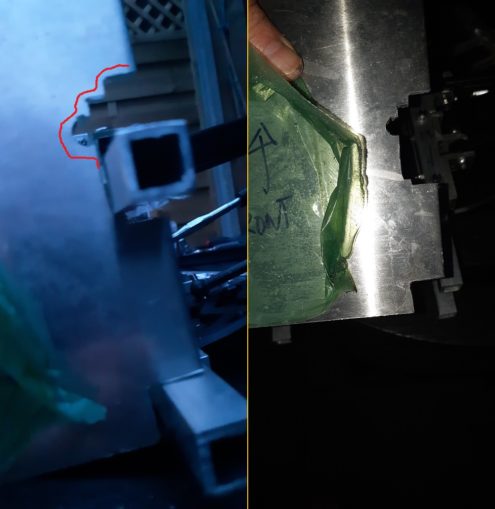
From right to left you can see the evolution of the piece – from right angle bends in the strip (the bracket is highlighted in red) to a flatter shape to give a bit more clearance away from the bloody great gearbox in the way. I could not contour the top of the yellow part of the gearbox as it had to be 3d-printed upside down so that the cavity for the actual gears was facing up.
As you can see, the red arrow highlights the travel of the steering arm, conveniently into the body of the gearbox. I could move the gearbox further away but I really need to keep the length of the car as short as possible.

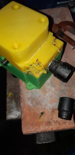
I hacksaw a chunk of the gearbox casing off, and chamfer the edges off.

And settle the piece back into place so I can see where the remaining crunch points are.

As ever, there is yet more to be done in removing material. I am once again having to refer to my 3d model of the gearbox so I can see just how much I can remove but still have the bearings inside properly supported and housed.
The Dremel of Dreams comes in very handy here, although there is a vinegar smell coming from the casing as I grind it down. It also burns the plastic something rotten but I can file that back to nice once the main bulk of material is removed.
One of the bolt heads is a little in the way and as I tried to remove it, I stripped the head so that I cannot turn it anymore. This is quite bad as the gearbox will need to be taken apart every now and then to top up the grease and check for wear.
Trusty Dremel to the rescue, I grind a channel across the bolt head and can use a standard screwdriver to remove the bolt.

I had to make a little bit of an overcut into the gear casing though which I am not happy about, but at least I got the bolt out.
Now that the gearbox is no longer in the way, and the steering servo can travel fully, the bolts holding the servo horn to the steering linkage are butting up against the servo holder.
Back to the Dremel again (have I mentioned how much I love this tool?) to remove a little material.

On the left I have finished, on the right I have just started. This was yet another load of taking everything apart which is getting quite tiresome now, especially as EveryThing is Either In The Way Of EveryThing Else or Moves Into EveryThing else.
At least I have the steering pretty much sorted now, and I can adjust the travel of the servo from the Tx set. Nothing is in the way now!
While I have the steering all taken apart, I round off the edges of the polycarbonate that links the aluminium bracket to the steering turnbuckle.

No prizes for guessing which tool I used for this job!
Now that the steering is pretty much complete bar adjusting the turnbuckles so that the wheels are straight, I can get the throttle servo connected to the throttle cable.
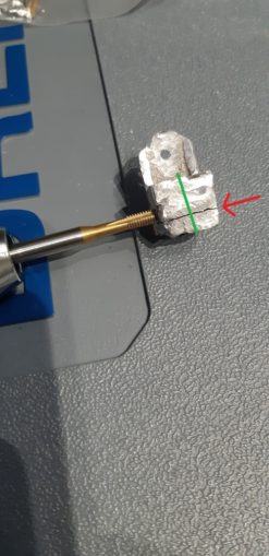
A little bit of box section and two bits of 5mm aluminium are brazed together and drilled and tapped. In the pic below, the small hole at the top is to mount to the servo horn, and the throttle cable passes through along the green line. There is another hole drilled in the block, at 90 degrees to the throttle cable that will hold a bolt that squeezes the cable to hold it in place.
Or at least, that was the plan…
While tapping the hole, the braze cracked. So back to sanding flat, a few grooves filed and then a whole lot of molten solder over the top and I am back in business.
Now for the acid test – is the servo powerful enough to pull the cable? I connect all the cables, offer a silent prayer to the god of Cnuts, and pull the trigger.
Success! The servo can pull the cable hard enough to move the throttle setting on the motor. I did notice that without very careful adjustment of the servo endpoint, the servo is going to be straining against the motor – the lever that is on the engine has a metal stop at full throttle. Obviously that is going to be bad for the servo, trying to move something which cannot move, so I go into my trusty box of springs (200) and add a spring to the mechanism, so that will soak up a bit of movement in the system. Otherwise I will have to be very careful to remember to check the throttle servo endpoint every time I race and that, I know, is asking for trouble.
During this evening time Cnuteneering though, when the light is poor and the hands and mind are tired, injuries are more likely. While I am usually reasonably safe, heavy duty gloves, eye protection etc, accidents do happen and this is the most severe I have had yet.

Bloody mossies! My calfs have swollen due to the reaction I get. I would probably call a halt to evening proceedings, but the compulsion of GQ is strong…
All control servos are now fitted and it’s time for some moving pictures, this was taken just before I did the second cut of the top gearbox case:
As you can see, my path is littered with the bitter fruits of failure. I think I will just have to double up on the spring (200) and see if that works.
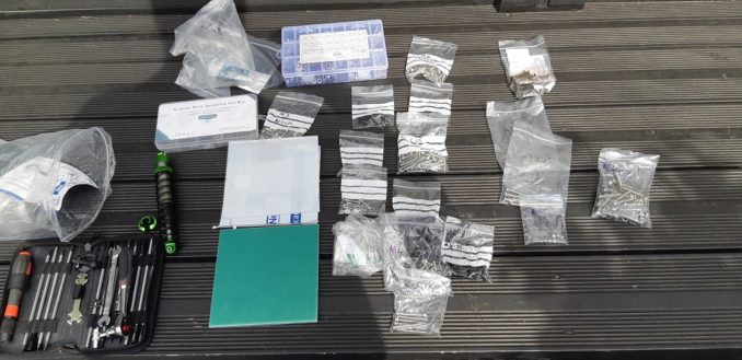
I have mentioned previously that one of the many challenges I face is the getting stuff out and putting it away again; this takes 20 mins out of time I should be trying not to injure myself with tools. Oddly you can’t buy a box of assorted bolts over 20mm it seems – all 3 of the boxes I have vary in size from M3 to M6 and a variety of lengths from 6mm to 20mm.
A lot of the bolting I do needs 25, 30 and in some cases 35 mm bolts so I have had to buy these separately. After getting skinned a couple of times on Amazon and eBay I started to use these folks for all my bolting needs at a great price with great service and a fantastic range of products and free postage for orders over £35 (*).
(*) yes I wish this was sponsored, too!
Now that I have the moving parts sorted out on the front end of the car I can start thinking about how I am going to mount the shock absorbers. First I will need a plate aluminium shock tower that will hold the top and bottom chassis rectangles together, and provide a rigid mounting for the top of the shock absorbers.
It will slide across the chassis rectangles and will therefore need yet more fettling so it passes over the bolt heads.
I really need to decide how to fit the front shocks to the suspension arms and the only solution that is going to work is to put a fork (a bit like a tuning fork) on the end of the shock absorber so that the drive shaft can pass through the tines. For that, I will need to remove the eyelet from the shock absorber shaft.
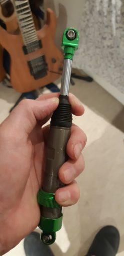
As you can see, the shaft is quite chunky and it is also very smooth. I tried undoing the eyelet with pliers, molegrips and even clamped it in the vice. I just could not get even the vice to grip hard enough to undo the eyelet.
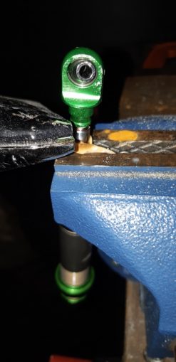
I did have some success from a puffin suggestion of using a heat ray (paint stripping hot gun) to warm any threadlock when I was taking the clutch bell and pinion apart previously, so I repeated this again. I used a rubber band wound around the shock absorber shaft in the vice, put the heat ray up close and finally success.
I have about 8mm of M5 thread to use to mount the shock to the shock fork, which will most likely need building from scratch. I need to have a think about how to do that though. Once I have that, then I can finish how the front shock tower attaches to the chassis.
In the meantime I can take another look at the drive train. I am not sure if these gears are properly level with each other – is it a trick of the light or are they off kilter?
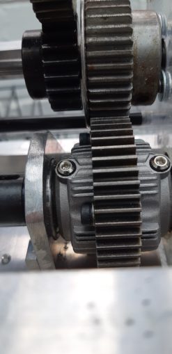
I do think I will need to beef up the support for the central diff bearing though, so in the pic below you can see the bearing coming through the araldite by about 3mm. In the background there is a 3mm plate with a cutout of the original gearbox plate blueprint, so I can see where all the holes need to be drilled. I can then bolt this piece on to the polycarbonate, and use the bearing glue to hold everything tightly.
Must remember to let the aluminium cool down as I cut it though otherwise the hole will not be at the right size.

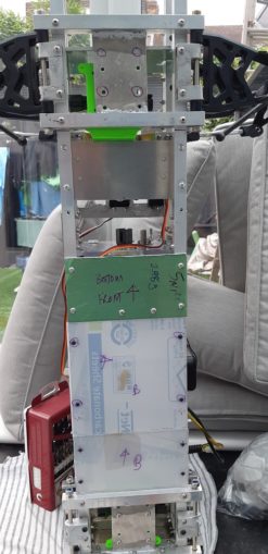
I finally get around to putting the bottom plates on so I have something to mount all the control electronics and battery to. Two plates, 4 bolts each.
A brief trip to my Braheelian mate and I have my new pinion gear drilled and tapped so I can mount it on the electric motor. The driveshaft is for the central diff to the front diff. I will put an M4 bolt through the holes and make a dog bone arrangement that way. I am not sure if I need to put a rounded end on there as well; I am thinking a short bit of 10mm steel pipe filled with JB weld, then let it go off and shape it into a ball. The JB Weld will also hold the bolt in place, too.
Suggestions welcome on that front, and as well, the bar is mild steel so I am not sure if it can handle the torsion forces it will be under. If I heat it to red hot and then quench it, will it give me the strength I need?

Who knows?
Still waiting for:
Replacement M3/M4 taps as the current lot are pretty worn
2mm drill bit to replace the broken one
Still left to do / think about
Design, build and fit the front shock tower
Design and build shock tower forks
End point adjustment for servos and control mechanisms Dumbo RC setup
Siting of RPM counters
Siting of battery and control gear
Bend the front of the chassis up or not?
Rear central driveshaft
Differential gearbox to wheel dogbone driveshafts
Attach electric brushless motor
Design and fit rollcage with picam mounting
Centre diff trueing and reinforcement plate
Pics, vids, words and music © El Cnutador 2021
The Goodnight Vienna Audio file


