Welcome back to Cnuteneering, where the possible is made more difficult by bone headed ignorance, overenthusiasm and pointy metal things being brought together. And poor couriering.
You may want to refresh your memory on the project in:
Part One.
Part Two.
Part Three.
Part Four.
Design goals:
Fast as possible on offroad; too big to have on roads. I will set a target speed of 50mph.
4 WD.
Must be able to reverse, and brake.
Unbreakable, or as close to.
Must be able to mount GoPro or similar camera on it.
Cheap as possible.
Again. very little actual building has been going on so far, just more bastard sourcing what I need. The lack of pinion gear (which I have totally not complained about, oh no) should not hold me back. As a punt on one of my other orders I bought a pinion gear, just a pinion gear instead of a pinion gear and clutch bell set WHICH I AM STILL WAITING FOR, 54 BASTARD DAYS AFTER I ORDERED IT. Probably more than that by the time this is published.
The pinion gears in this scale (1/5) are either stepped or hex mounts. A stepped mount pinion looks like this:
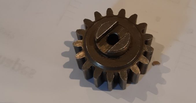
The inner hole is 4mm diameter, the depth of the step is 3mm by 5mm wide. The clutch bell I do have is just a shaft with a 20mm threaded 6mm hole inside.
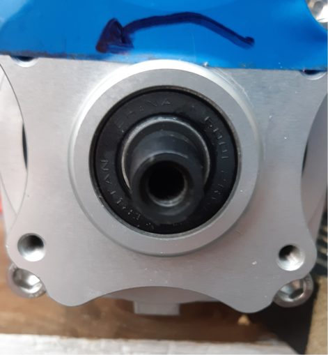
So I can grind the edges of the drive shaft down, and drill the gear out to be 6mm and I should be good to go. I am somewhat reticent to do that just yet as I have been in contact with the pinion supplier who has allegedly shipped another. Dec 16th, allegedly. At least this time around, it has been accepted by airline rather than languishing in a warehouse.
In the interim, I have the ally box section to play with so I lopped off a little length (!) and drilled it with a 5mm hole for a 6mm thread. I need to know if I can easily thread into the bar, and how strong it is.
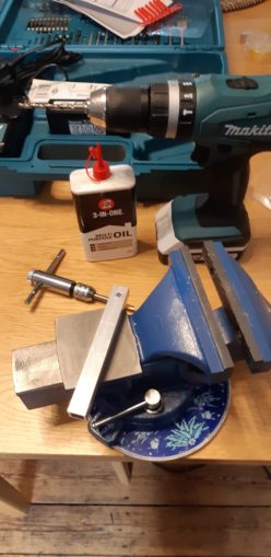
Here we have the tools ready to go. I have already drilled a 5mm hole in the aluminium box section, the vice is getting it’s first outing. On the table the M6 x 1.0 tap is mounted in the wrench and I have a big bottle of lube.
I have no cutting grease so 3-in-1 oil is as best as I can do. A bit like RP on a Friday with his block of Lurpak I suppose. The thread cutting is pretty quick and painless, three twists in, one twist back so the swarf gets cleared properly. Cue engineering Holy War – “three forwards two back”.
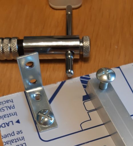
Metalwork is harsh mistress.
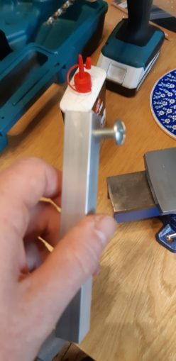
However here we see the difference between metal and wood. I am 1mm out of orthogonal and the bolt will not go through both holes and looks a bit on the piss. Hence the drill press to keep me nicely at right angles.
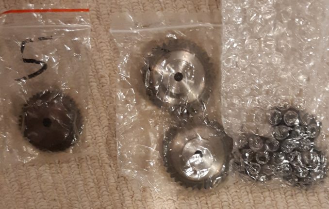
While all of this has been going on, someone in Chy-na was happy enough to take my money and send me the gears. Little baggies of engineering happiness plus a generous extra set of grub screws. These are little headless screws that go through a threaded hole in the gear collar and allow the gear to be bound to the shaft.
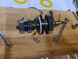
The gears fit nicely together, some bound to the shaft and some left free wheeling. Putting them together for the first time was somewhat satisfactual.
For those paying attention the gears are marked with their IDs on this closeup:
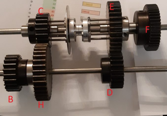
Gear B, H, D and F all rotate with the axle / shaft, as well as the dog tooth (no sprockers harmed in the manufacture) gear between free wheeling gears C and E. I still need to drill some holes in C and E to accept the bolts (and probably smooth the bolt threads down for slicker operation). The giant washer mounted on one of the hubs gives me a nice clean edge to push left and right with the gear change mechanism, from any angle I can get away with.
You can see how the width of the collars keeping C and E gears are pretty wide which means the bolts coming from the dog tooth are long, and hence weak. If I can cut a thin groove on the axle there instead I can put a circlip on which is much lighter and thinner, the bolts can be shortened massively.
One worry I have is that the silver hubs are bound to the axle loosely with a grub screw. This will be superglued in place so that the hub can still move up and down the shaft to engage with C or E but I am now concerned that the whole weight of the mechanism relies on that point as a single point of failure, which will be heavily stressed as inertia is to be overcome when the car starts to move.
Another worry is that the gears alone weigh 1.1 Kg. That is _heavy_, man. And weight begets inertia. Hmmm. I may have to drill large bore holes through the gears to drop their weight but I will hold back from that for now.
And so, back to sitting like a lovelorn spaniel for the postman to bring me a pinion, I wait. In the meantime, now that I have the gears, I can lay them out on the perspex such that there is a tiny gap between the gear teeth that mesh, and the output differential is far enough down from the engine pinion gear so the driveshaft can pass under the engine. Then I can get some holes cut for the bearings and build the gearbox mount. This will be bolted directly to the clutch bell housing on the engine.
I will then have a definitive engine / gearbox block so I can then calculate the car length, and hence width. And finally get an engine mount cut and ready to sit on the chassis. Which I have yet to design.
Still to be designed:
Rack and pinion for gearbox servo?
Rack and pinion for steering servo?
Suspension arms and wheel mounts
Brakes / reverse gear
Still needed:
Pinion gear clutch bell should have been here between Oct 27 – Nov 16. This is late you bastards!
Servos x 3, one powerful, one reasonable, one weakish
Steering 60-65kg but 45kg is stock for most 1/5 cars
25-30kg throttle
<10kg? for gear select
Servo saver for steering – this breaks cheaply when you crash instead of the expensive servo gears.
Shock absorbers.
Drive shafts from central diff to front / rear diffs and from front / rear diffs to wheels.
Pics, words and music © El Cnutador 2020
The Goodnight Vienna Audio file


