Welcome back to Cnuteneering, where the possible is made more difficult by bone headed ignorance, overenthusiasm and pointy metal things being brought together.
You may want to refresh your memory on the project in:
Design goals:
Fast as possible on offroad; too big to have on roads. I will set a target speed of 50mph.
4 WD.
Must be able to reverse, and brake.
Unbreakable, or as close to.
Must be able to mount GoPro or similar camera on it.
Cheap as possible.
We left the last episode of Cnuteneering finally getting the front shocks and suspension put together.
I now need to pick up on all of the little leftover project pieces that need finishing.
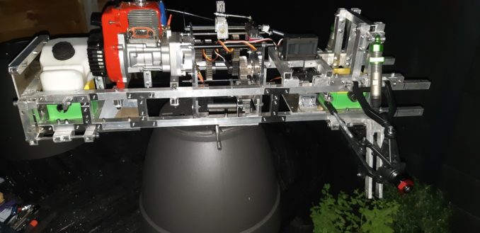
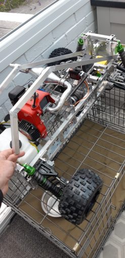
The central diff is now mounted and ready to accept the drive shaft to the rear diff. The electric motor is also mounted too. I have not loctited everything into place or used the bearing glue as yet; I need to get everything just-so before I commit to that.
I fit the springs back on the shock absorbers for the front, pausing only to admire how perfectly well cut the end points of the fork are.
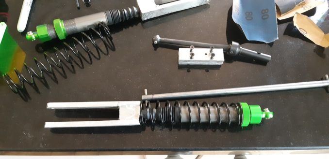
They are not as ugly as I was expecting them to be when fitted at least!

So that is all of the little jobs left to finish before I embark on the next bit component – the front bumper. Now this needs to be a little behind the furthest point of the front wheels, if I want to be able to go up kerbs successfully.
So I fit the front wheels so I can take some careful measurements.

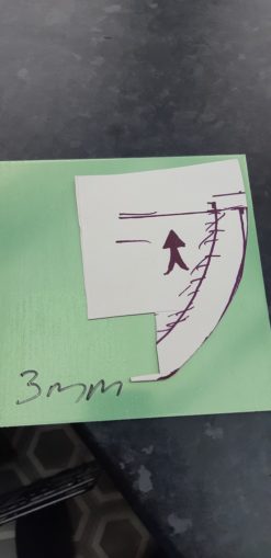
I can now get started on the bumper design. This part of the car is going to take a beating from my ineptitude when driving, so I make it out of 3mm aluminium plate.
A bit of faffing and a couple of redraws and I get the design just about right. I would like the curve to be gentler, but I am constrained as to how much I can go forward by the front of the wheels.
At this point in time, you tubers go to their garage workshops and put the metal plate into the metal bending machine and they are done. This being Cnuteneering though, I have to make my own.
3mm plate is actually stronger than you’d think when it is 150x150mm in size, you get next to no leverage on it. So I need some way of holding it still while I bend it by hand.
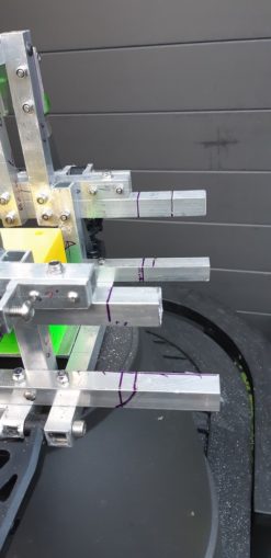
And here we have the mk1 CnuteneeringMetalBender:

I have clamped some steel bracketing on to a couple of bits of 5mm thick scrap aluminium offcuts, to the workmate. The piece has multiple parallel lines so as I bend through the piece I am always bending it true.
That was the plan anyway, the workbench began falling apart as I began pulling at the metal; the clamps just dig into the wood and absorb the tension I apply. I end up very sweaty, with sore (soy) hands and a piece of metal that looks exactly like it did ten minutes ago.
No solution to it then; into the bench vice to batter it with a wooden mallet until it be shapely.

And shapely it is; you can see the edge of the aluminium just poking a little above the line of the cardboard template. Not bad for freehand, and more importantly, the curve is level across the width of the metal and the ends are 90 degrees rotated. Close enough for Cnuteneering!
Now comes the 5p-50p ringpiece moment – cutting the chassis back to fit. Bear in mind this is one of the first structural components I made and it has had countless hours pumped into it to date; it is one of the most valuable pieces on the car. If the fuckup fairy comes calling on this one, I might as well put the whole lot in the bin and redo from start.
No pressure then!
The chassis is cut, holes are drilled and the bumper is fitted. Looks pretty good I think!
Now on to the finishing of the transmission; I have some 8mm bar ready to cut, drill and tap to put the drive lugs in and I should be able to power the rear wheels for the first time. I have just enough to make all of the drive shafts once and about 5mm left over.
No pressure then!
Unfortunately I break my 2mm drill in the steel and struggle to get it out.
This is quite bad, not because I bust my drill bit (I have spares from 2mm to 5mm now!), but because this is the last bit of steel I have in my shed. Supplies of other materials are dwindling too; I have no more 3mm, 4mm plate, I am nearly out of several lengths of M3/M4/M5 bolts. I have my last 2m of box section and one bundle of brazing rods. There is a certain fin de siècle feeling about it when I open the shed door.
If I can’t get this out then I will need to order and wait for another bit of 8mm steel rod which will crimp the plans horribly. I manage to file a little away and use the punch to push the drillbit out enough to get some pliers on it to pull it out, although not without a small blood sacrifice; shatter drill bits are _sharp_.
The rest of the shafts were built without incident, drill 2mm, drill 3mm, drill 3.5mm, taper tap, second tap, plug tap and then grind an M4 bolt head off, threadlock it in place and put a couple of thin nuts either side.
Taking care to avoid confusion on #FF night, I liberally grease up the rear diff and give the bolts a tighten back up. Lovely job!
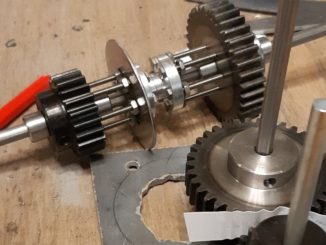
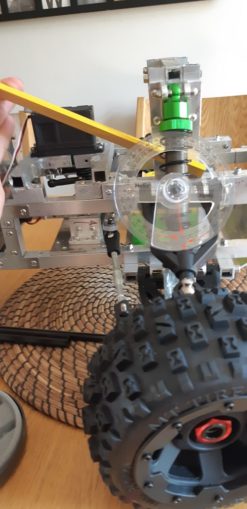
So we are doing quite well now, from engine and motor we have power all the way to the rear wheels, and up to the front differential. Diligent puffins who have followed the series and not ruined their short term memory through excesses on #FF will remember that the front wheels have Constant Velocity joints at the wheel end, and the drive shaft that comes with them is woefully short to connect in to the front diff gearbox.
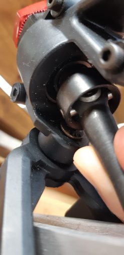
This shows up close how the joint is put together, there is no way I am going to be able to machine that on a workmate on my back patio in my luxury well appointed state of the art workshop.
There’s some useful pics and videos to be seen here if you’re interested further.
In any case, the only thing I can do is to try to extend them into the diff gearbox as best I can.
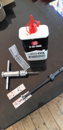
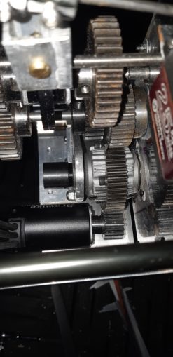
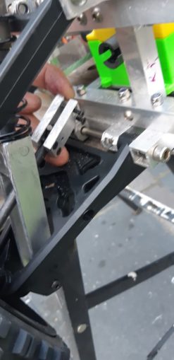
Here you can see 2 plates, with a groove cut for the shaft and a socket for the ball end (filth). I am struggling to get the groove cut nicely as I can’t push a file too far at the centre, just the diameter of the socket hole at a time. It is only when I put the pieces together and bolt them tight, I realise I could have done that and then just drilled down the centre to give a nice channel that is the right depth.
I am pretty chuffed with the socket holes though – I started with a 2mm hole through both pieces so I know the centres are aligned. I then drilled a long way in with a 3mm bit, then less far with a 4mm, then less far again with a 5mm and so on until I reached the 12mm diameter required. Holding some emery paper over the ball, I spun it in the socket until nicely polished.
And here we see it in place.
I just need to add a little of the 8mm steel bar to the other side of the extender, and I am done, drive to all four wheels which will be nice. I think these are going to be spinning at several thousand RPM though and the block looks a little unwieldy for now. I shall put this on to the Later pile; I have a solution but it is probably not the best.
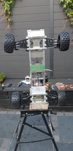
On the plus side, I now have all four wheels on the car and the means to drive 2 of them.
The wheel toe-in needs adjusting but this is just a few turns on the steering turnbuckle.

At this point in time, I am sunburnt, my hands are dirty and sore

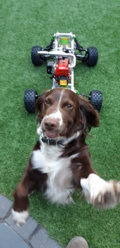
And it is spaniel time (Sozzinski was bemoaning the lack of spaniel in the last episode).
Now that the car is largely built I need to work out how I am going to put a roll cage on to it. Eagle eyed puffins will have noticed the spark plug sticking out the top of the engine, which anyone who has driven an RC car will know also comes with an implicit “BREAK ME” sign flashing above it. I need to protect that, and the steering servo, gear change servo et al for when I roll the car.
Some designs present themselves:

The first is a little too fussy, the curve in the middle is elegant but would be a bastard to make as I cannot bend square box section easily and nibbling segments out to bend the pipe then brazing them shut would take forever. So option 3 is the only viable course.
A bit of wood from the SHED OF POWAH and a borrowed protractor and I am away:
I take measurements of the inside of the rollcage that will also suffice as the cockpit for the car.
And now – time for the workings out!

I have the inside measurements of the arc, but I need to calculate the outside measurement as it is the longest and will need careful measuring.
So I measure, and cut the Vs in the material with equal sizes each side so that the inner edges will meet so I can get some more braze solder in there for strength.

And here we are, bent and re-measured with the protractor. I pencil in lines on the bricks where the box section should go, so if it unbends when heated I will know to stop as the shape is wrong.

Brazed, cooled and finally I can check for fit:
Somehow I managed to balls up my calculation on the rear section and it is about 60mm too short. Looking at my sheet, somehow I managed to get an utterly wrong hypotenuse from the opposite and adjacent sides. I blame the heat on Sunday. This is not irretrievable, I can braze a section on to it and I need to put some cross pieces in as well so that the roof top comes off as one. But still, schoolboy error on my part, fat fingers on the calculator perhaps? Either way, the hypotenuse should be longer than either the opposite or adjacent sides but it isn’t.
The plan is to have several flat sheets of thin (2mm) polycarbonate in each section – one down each side and across the 3 top sections. To attach these it would be nice to have some little bolts like these:
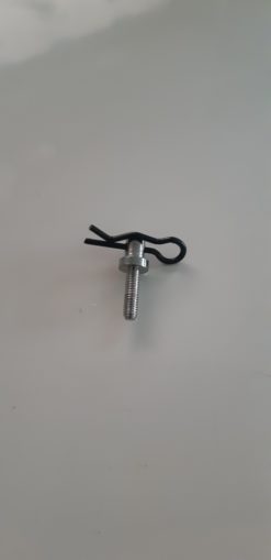
The threaded part goes in to the canopy frame, leaving the round stud poking up. I can drill a hole in the polycarbonate body shell, push the stud through and then fasten with the R clip to hold the sheet in place.
Can I find these? No, is the short answer, despite the assistance of some kindly puffins.
In the meantime, I still have to finish the canopy to rectify my mistake and put the cross pieces in, work out how I am going to sort out the extender for the transmission to the front wheels and Loctite the central differential gears in place. I have another idea for the extender but I need a piece of aluminium pipe to be delivered.
A little bit of adjustment and faffing and I am quite close to my test run once I get the electrics in. Do I wait until the telemetry pi is attached and wired in, or do I just try a little pootle around the back yard?
Choices, choices. But we finish this episode on a high note, the THTTARN pile is gone. It is all coming together and the end is in sight.
Still waiting for:
18mm aluminium pipe
Still left to do / think about
End point adjustment for servos and control mechanisms Dumbo RC setup
Siting of RPM counters
Siting of battery and control gear
Differential gearbox to wheel dogbone driveshaft extender
Loctite gears in place
Finish rollcage with picam mounting
Body shell
Pics, vids, words and music © El Cnutador 2021
The Goodnight Vienna Audio file
Is missing as fromtextospeech.com is down.