
Welcome back to Cnuteneering, where the possible is made more difficult by bone headed ignorance, overenthusiasm and pointy metal things being brought together.
You may want to refresh your memory on the project in:
Part One.
Part Two.
Part Three.
Part Four.
Part Five.
Part Six.
Part Seven.
Part Eight.
Part Nine.
Part Ten.
Part Eleven.
Part Twelvety.
Part Thirteen.
Part Fourteen.
Part Fifteen.
Part Sixteen.
Part Seventeen.
Design goals:
Fast as possible on offroad; too big to have on roads. I will set a target speed of 50mph.
4 WD.
Must be able to reverse, and brake.
Unbreakable, or as close to.
Must be able to mount GoPro or similar camera on it.
Cheap as possible.
We left the last episode of Cnuteneering at the exciting point of rebuilding the gearbox but in what I thought were forever positions – everything cut to size, gear changer proof of concept built and installed and mostly working. During the testing though the gears are pressed too hard against each other so are rubbing on the shafts and not turning freely.
I have no idea if I mis-measured, mis-machined or just got something else wrong, but the solution is just to move the shafts a little bit further apart. Buoyed by the success of the clingfilm condom I used previously, I took the gearbox apart, shedding but one manly tear for the wasted threadlock but thankful I had used medium strength not heavy duty.
Filed, taped and with the bearing wrapped safely in clingfilm, we are ready to go. A cocktail stick in there to push the bearing in the direction I want it to be and hold it there, and we are off for some more waiting for the glue to harden before I can see if I have moved the bearings enough.
Which will mean putting the gearbox back together _again_.
Whilst returning to my favourite pastime, waiting for parts – in this case the veroboard and 2×20 connector, I rework my Pi code so it can be integrated into the raspivid app. While doing so I realised that in order to get the RPM sensors correctly aligned, I would need a test app.
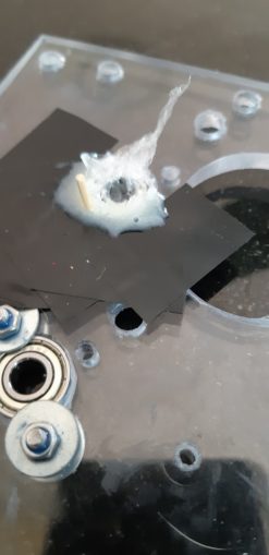
The idea is that I put a reflective strip on whatever is rotating and that is what I use to bounce the laser back into the sensor. I already know that this works, but I am going to have to encase the electronics in some sort of rigid manner (probably epoxy) to hold them together as the car is in motion.
The sensor has two little metal pins coming out of it that can be bent to adjust, but I need to have a way to see the Pi is noting that the laser is hitting the sensor – angles of incidence and reflection and all that. I can’t just spin the engine over and hope that the sensor is aligned correctly.
So here is the code for the test harness:
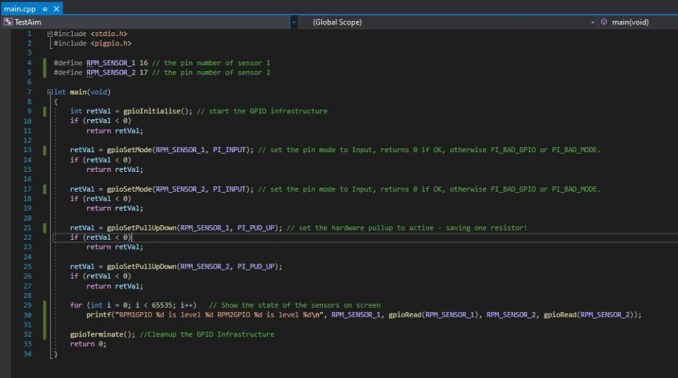
Fairly straightforward stuff; if it is not then Learn To Code!!!
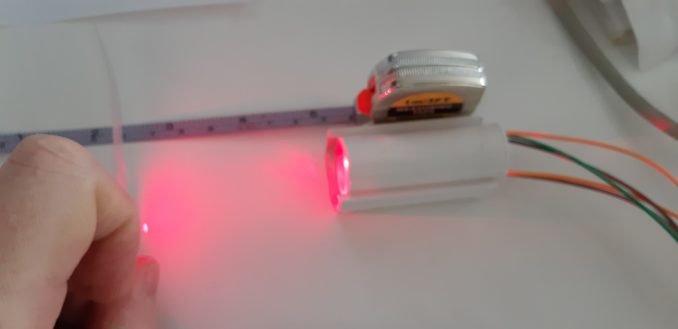
One thing I also need to check is what sort of range is viable from the sensor to the reflective pad. Using my state of the art calibration tools I determine that from 0-5cm the sensor is rock solid, at 5-10 cm it is a little flaky and at about 13 cm it stops working so well. Useful info to have.
I am pretty much done with the telemetry and measuring aside from fitting it to the car, and once the veroboard and 40 pin socket arrive I can take the unit apart and fit everything back into place. Yet more disassembly / reassembly to be getting on with but I hope it is not as many times as the gearbox…
Looking at the Pi specs and reading online, the Pi is not well suited to capturing sound. While it would be nice to hear the throaty roar of the G2D Zenoah engine at full pelt as I coast at 65MPH on rough terrain (hah!) it looks like the processing overhead and hardware ask is going to be too high.
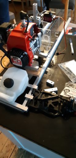
On the subject of which, now that the gearbox is fully sorted out, I can _finally_ put it onto the chassis and mark our where stuff is about to go.
Starting from the rear of the car, as the front is kind of designed but not really finalised. There still remains too much faffing with the steering still to be done which I can’t really do until the bottom and top frames of the chassis are built and I can work out just how far apart they need to be.
First things first, I need to get something to hang the bottom suspension arms off. I am thinking a fixed (welded or bolted) central block, and two removable front and rear pieces that will hold the shafts for the suspension arms.

Here I have included the differential gearbox that will feed the driveshafts to the wheel hubs. It is about a 15cm gap in there which is a bit of a worry, and the 7mm sockets will need supporting when fitted to the drive cups that come out of the sides of the differential.
That is going to be interesting as the support will be right over the central suspension arm block. Another for the THTTARN pile.
It does mean though that I can finally place the engine block on the chassis frame and mark how far forward the front plate of the gearbox is, with the first accurate measurement of where that is. Some fans are on the pitch, etc. A reminder to myself that the Rovan car is 81cm long, 52 cm wide with a 55cm wheelbase.
Stats for the HPI Baja, the Rolls Royce of the 1/5th RC car world:
Length 817 mm (32.2 in)
Width
Front: 460 mm (18.1 in)
Rear 480 mm (18.9 in)
Height 5.20 in (132.1 mm)
Axle track
Front: 395 mm (15.6 in)
Rear 400 mm (15.7 in)
Wheelbase 570 mm (22.4 in)
Weight 9.6 kg (21.2 lb)
At the moment I am looking at these stats for the Cnutmobile:
Length 770 mm
Width
Front: 620 mm
Rear 620 mm
Height Still unmeasurable
Axle track
Front: 550 mm
Rear 550 mm (15.7 in)
Wheelbase Still unmeasurable
Weight I don’t even want to think about it
At this stage I am really not sure whether to have the long pieces above or below the bottom chassis. In the above pic, they are above but that is mostly for convenience.
Having them below is better as the weight of the car just pushes them together and on to the wheels, so they will just need bolting together to keep them where they should be. They won’t be in the way of the diffs which is also a bonus.
They do however, break up the line underneath so will be prime targets to be ripped off when I am going over rough ground unless I put some kind of plating over them. If I put them above, then the bolts / welds will have to bear the weight and momentum of the car as well.
For now though, this is THTTARN.
I get to cut some metal, front and rear long pieces plus four central blocks that will be brazed together.
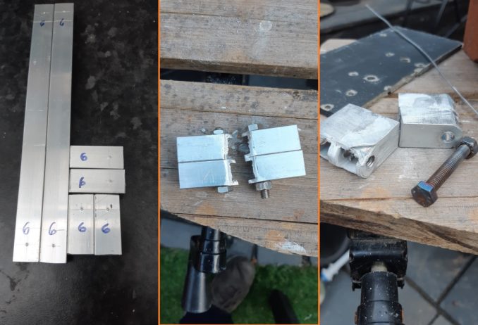
In the above exciting action shot, I have cut and marked the places where I need to drill holes. I have found that to reduce drill skitter, put a massive big pilot dent in the aluminium, start off with a 2mm drill and then go to the 6mm drill. I have some other holes to drill so to prevent confusion in the heat of construction, each hole is marked with a 6 so I know it has to be 6mm.
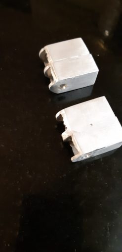
The central pic shows how I have bolted the two blocks together prior to brazing. This holds them nice and still and the braze goes mostly well apart from not noticing that the other block was too close to where I was brazing. With my attention focused on the braze, I failed to see the flame was busy melting the other block.
Not too badly damaged I hope. They did polish up nicely, anyway.
For some reason, having the two flats together seems to be quite an easy weld to make. Not so much for the 45 degree joints I need at the back.
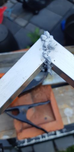
Still, I managed to get the three pieces all together in the end, and the mess of the weld can always be angle ground down and filed to niceness.

This being Cnuteneering however, something inevitably goes wrong and here we have it:
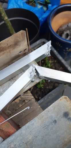
Just in time for the gas to run out for my brazing torch. About now MBWK is getting the dog with me faffing about with the car stuff at the weekends when there’s other stuff I should be doing so a little hiatus is needed to restore some familial harmony.
Every now and then a little doubt creeps in on the viability of this; I have lost count of the hours spent learning how to do things, designing and redesigning things, and I daren’t think of the sunk cost so far, probably about 6-700 quid so far. I could have bought a brand new CCP knockoff for that where everything works, fits properly, and the engine is properly tuned for a fast car.
Dejectedly I retire to the comfort of the sofa and El Woofador comes over with his boundless enthusiasm which never fails to cheer.
Will I ever finish this bloody car? I am tired of re-iteratively building and rebuilding the gearbox, tired of not having the right tools and tired of the project at the minute. I’m tired of having to tidy everything away and hope I file the parts in a box I can easily remember and find again, and get it out again each time I do some work, of having no cheerleaders celebrating the minor victories or commiserating when things go wrong. The iterative see if this works then build properly model is taxing on the enthusiasm, as a proof of concept moves to a final piece but where all the fun is stripped out. My workbench is an old workmate with a drill press that bends and a vice whose jaws don’t close perfectly parallel and I can’t use it if it is raining because my workshop is just a corner of the back patio where I put a power outlet in so I didn’t have to keep running extension leads.
The veroboard arrives and then a day later the 40 pin sockets.
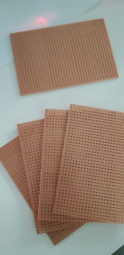
Veroboards like these have copper tracks on one side, and lots of holes to poke wires and legs of components through so you can then solder them to the tracks and make the connections.
Not as good at soldering as I thought I was, the gas soldering iron I have is good but it vents heat out the sides. Hot enough to burn the copper track off the veroboard. One more tick in the fail column.
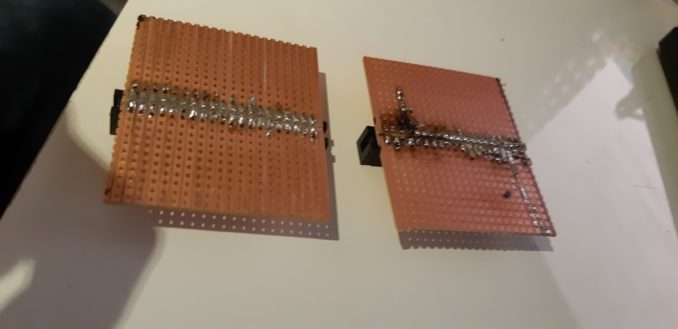
I use the AVO to test that I have not inadvertently tracked solder between the pins and copper rails, and verify that the pins in the socket are indeed connected to the track on the left hand side board.
I consult my Pi pinout diagram, and verify that the pins I have are indeed the pins the Pi thinks they are – the possibility of the pins being transposed and 5v going where it should not will ruin the Pi. And then double check with the AVO that pin 1 is indeed pin 1. I discover that my cobbler is not connecting the 3.3v pin to the cable which is news; just as well I have not had cause to use it as yet.
More AVO checks and I now have the pull up resistor soldered to the board as well for the temperature sensor.
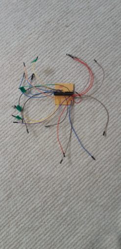
I have gone for a fetching colour scheme of red/brown for +5v, blue/black for GND, green for oneWire component signals and yellow for bog standard GPIO connectors for the RPM counters. I also added an extra +5v / GND / GPIO cable in case I might need it in the future to add another sensor. All sensor cables are sensibly marked with pin number and GPIO number so I don’t have to take the unit apart again for some time I hope.
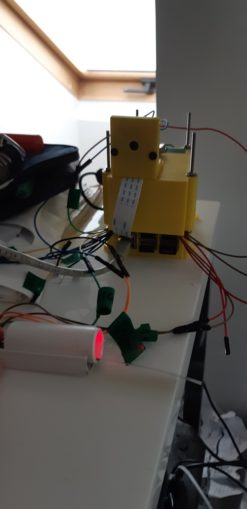
Everything is plugged back in again, I fire up the Pi and my test harness programs to verify everything still works, temp sensor, RPM sensors and GPS.
All systems functioning within normal parameters.
But, over 6 hours to redo the whole telemetry box that was in full working order before I started. Six hours to effectively make no real progress.
It’s all so tiresome.
Still waiting for:
Long M6 bolts and vibration proofed M3 / M6 nuts
Still left to do / think about
Sort out the car underside – at the minute it is just a gaping void
End point adjustment for servos and control mechanisms Dumbo RC setup
Siting of brakes
Need to build the brakes as well I think!
Finish RPM counters
Siting of RPM counters
Integrate code to read sensors, temperature and RPM into the video capture
Front end siting of servo and steering yoke
Siting of battery and control gear
Pics, vids, words and music © El Cnutador 2021
The Goodnight Vienna Audio file


