Welcome back to Cnuteneering, where the possible is made more difficult by bone headed ignorance, overenthusiasm and pointy metal things being brought together.
You may want to refresh your memory on the project in:
Part One.
Part Two.
Part Three.
Part Four.
Part Five.
Part Six.
Part Seven.
Part Eight.
Part Nine.
Design goals:
Fast as possible on offroad; too big to have on roads. I will set a target speed of 50mph.
4 WD.
Must be able to reverse, and brake.
Unbreakable, or as close to.
Must be able to mount GoPro or similar camera on it.
Cheap as possible.
We left the last episode of Cnuteneering at the vinegar strokes of getting parts and then not. Undeterred by that and surgery, I worked out at least that I can get to work on the brake mechanisms. After looking at some brakes online, for 1/8 scale cars, it looks like I need some sort of cam in there which I can machine to size. The HPI ones look like they are hard to get, plus I would need to buy 2 sets of them in order to get the length of shaft I need.
After some solid advice from Grimy Miner who kindly talked me out of getting a metal milling machine, I resolved to at least design the parts in 3d and then I can hand that over to people with the heavy duty precision gear to CNC manufacture. All I need to do is send a file with the design, in .iges, .STP / .step or .STL format. These are just vector based files that describe the overall shape of the object and firms will have CNC software that can read those and turn a block of metal into the shape required.
Like these folks:
There now follows a big step of finding some other free CAD design software that isn’t Fusion 360. Nothing against that product but the learning curve is a bastard and the online tutorials are way above my head for what I am doing.
I did find FreeCAD though and gave it a go. After about 10 hours of faffing, I finally came up with this:
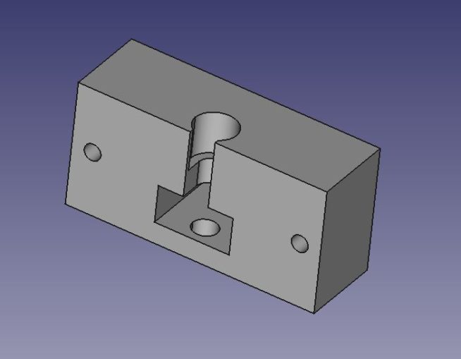
The idea is that the cam will pop into the pocket, I can place a flanged bush over the top (a bit like a bearing with a flared lip) that will hold the top and bottom of the shaft in place. The cam shaft can have a bolt in the top at right angles to the shaft which the brake servo will pull via a cable, which turns the shaft around in the pocket and forces the brake pad into the brake disc to slow it down from rotating. I can machine this with a saw and a bench press drill.
First though, I need to get my metal \m/ workbench built.
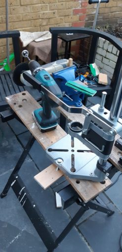
Here we have the vice, in machine shop blue, a Makita (cue tools Holy War) battery drill, and the drill press which is firmly mounted to the workbench with a wooden backplate and a couple of bolts drilled through the base near the drill column, to try to stiffen it so it does not bend like a reed when moving the drill up and down. I also removed the spring from the drill press as the tension it was providing was enough to bend the column just by pushing the drill lever down with no work piece present to push against.
Eagle eyed readers will have noticed the battery drill has something in the chuck. As part of the gear change mechanism, I need a round sleeve to fit over the hex bar that the gear engagements run across, for the gear changer to ride over. Unfortunately the big fat washers I got are a little small internally and more unfortunately, are of trapezoid cross section.
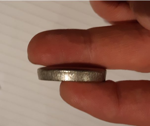
After marking the vertexes of the hex bar on the internal diameter and filing down so the hex bar fits through, I can mount the washer on a hex bar, which has a hole drilled through it, and then use the grub screws to bolt a shaft in place. This shaft can then be gripped by a drill chuck, and sanded until the profile is square while keeping it perfectly round (ish!).

So the first cutting with my Cnuteneered metal table saw is to take a strip off the edge of the aluminium block to use to make the brake cam shafts. Here, the angle grinder blade is trued to perpendicular to the table, a guard block is clamped so there is 18mm between it and the left side of the blade and the work is free to be pushed into the blade.
Given that the guard is off of the grinder I take extreme precautions – heavy leather gardening gloves and a full face engineering visor. I have tightened the blade on the grinder very tightly and I am wearing my heavy leather jacket, a chunky padded hooded top; if anything flies off the work or tool I should be protected.

The cut goes reasonably straight but not quite as planned:
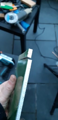
It looks like the thin strip is catching the blade and bending it a bit. Also note that the saw does not have much length available to it – about 100mm is as long as I can cut before the vice gets in the way.
Re-setting the table saw for a 6mm cut, and a bit of hacksawing for the short cuts, eh voila!
I need circular a shaft though, not a 6mm x 6mm cross section. So, time for more Cnuteneering – I shall build a metal lathe!
Considering how a lathe works, it is a pointy bit that stays still, and a spinny bit that goes round and round holding firm to a bit of work. Looking at my workbench I either have or can fashion those two components.
And here we are – the Mk 1 CnutLathe:
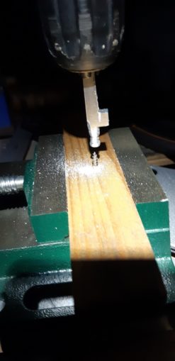
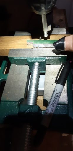
The “point that is still” component is a screw driven through a bit of wood from the Shed Of Powah, held in place by a small vice. The drill is mounted on the drill press and pushes down with it’s weight so I have both hands free. The brake shaft is gripped by the drill chuck. Neat, eh?
I just need to start the drill and apply an abrasive to the shaft, which I have used the angle grinder to flatten the corners into an octogon. And here we hit the first problem.
The drill has an always on lock button that locks the drill into full speed without the need to keep pulling the drill trigger, so I can have both hands free. This rotation speed is however, quite fast and too fast to really get much traction on the piece with an abrasive. The trigger has a dial on it though which I mistakenly thought was a speed setting.
It is not.
Every day is a learning day in Cnuteneering though; turns out it determines how much force the drill is prepared to face before the clutch slips. Bugger.
So I am now trying to hold an angle grinder in one hand and squeeze the drill trigger just a little in the other in order to make my cut. This is more than a little tricky so I give up after a little while, for now at least. I need some way of setting the drill to slow speed, either a jubilee clip tightened just so around the trigger or some variable voltage controller to the drill.
My attention turns to the assembling of the suspension arms to the knuckles / hub carriers. This is going to need a bit of Cnuteneering as the front arms are designed for 2WD. I can just about fit a 30mm bolt into the steering knuckles, but not 35mm which would be better. In the picture below you can see the two parallel faces of the knuckle – I need to get a countersunk head bolt in there. The material at the bottom is not thick all the way through; there is just about half of the depth of what you see here to play with.
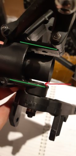
The red line shows how far above the knuckle the bolt head protrudes – if I can get this 2mm further down then that’d be a win. I cannot countersink it from the top because the countersink drill bit is longer than 30mm, so what I need is a countersink that cuts towards the point of the shaft, instead of away from it. If I cut a couple of angled grooves in a short screw head, I could use that to cut a countersink into the knuckle and get that vital 2mm of plastic out.
Back out to the back patio machine shop to cut some screw heads up. I am tired, it is getting dark and I want to pack up and get started on dinner. Machine shop regulars will recognise this chain and this is why the guard stayed off the grinder and the gloves stayed put in the shed. Skidding off the screw head with the grinder, I caught the edge of my thumb on the blade and made a small cut. Incident report duly filed and noted but the Cnutmobile has claimed it’s first blood. Thoughts, prayers and tealights from the puffinati certainly helped though and it is mostly healed now. Observant puffins would have seen the wound bound in the #manlyfirstaid fashion in the second pic of the lathe.
Some research was done on how to get around my front shocks getting in the way of the driveshafts. Converting an FS Racing car to 4WD at around 40 min it is revealed how it is done – the suspension shocks have a fork instead of an eye fastening, it would appear, like in this part.
That of course, completely blows my cunning plan out of the water as I am going to have 15mm driveshafts in the way there. I shall file this under “too hard to solve today”.
Now that I have a workable brake cam, and playing with it a bit, it feels way too weak to really put the anchors on. Given that this car will be over 20Kg and moving at 50mph (he said with crossed fingers and a silent prayer to the God of Cnuteneering) the brakes really, really do need to work.
Back to my new found friend, FreeCAD, for some virtual Cnuteneering.
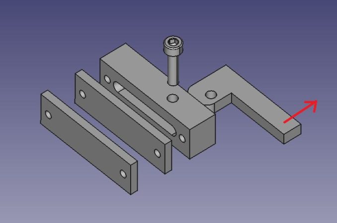
This looks easy to make, and has a much stronger cam arrangement. The brake cable will pull in the direction of the red arrow, causing the cam plate to rotate around the bolt that goes through the main block.
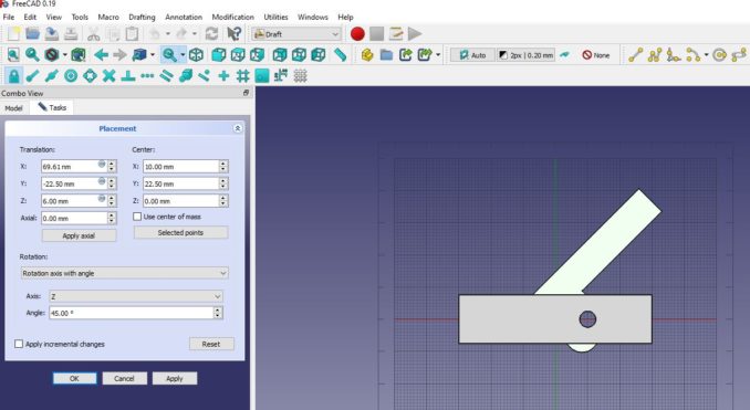
In 3d modelling I can rotate parts around to see what they look like, and it looks like the cam lever needs to move a long way to get just a little protuberance from the main block.
Back to the drawing board for the next try:
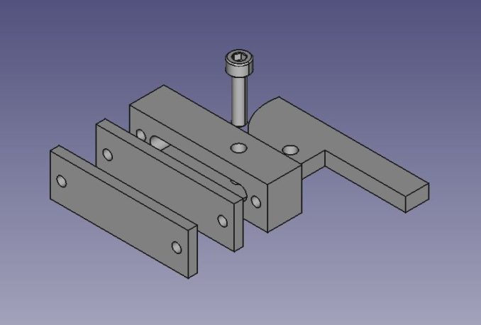
The cam plate is much beefier, so let’s try it in a few angles and measure how much cam protuberence I get for lever movement:
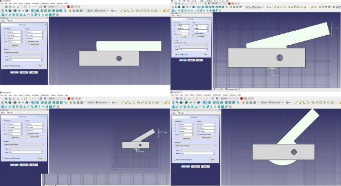
For 15 degrees of pull I need to move the lever about 10mm via the brake cable, and I get about 5 mm of push on the cam. At 30 degrees, I need to move the brake cable 18mm and I get almost 7m of push from the cam. At 45 degrees I will probably have broken something. I reckon the servo can do a 20mm pull on the cable, so that is all good I think. This certainly beats mucking about with bits of cardboard!
Some fancy pants animation, all my own work:
So now I can get an idea in real life of how stuff is going to fit together, laid out on the dining table:
Seen from above, the petrol tank will eventually either sit behind the engine or on top of the central gearbox:
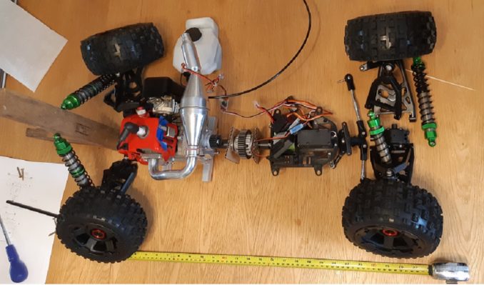
From the side:

From the side at an angle:
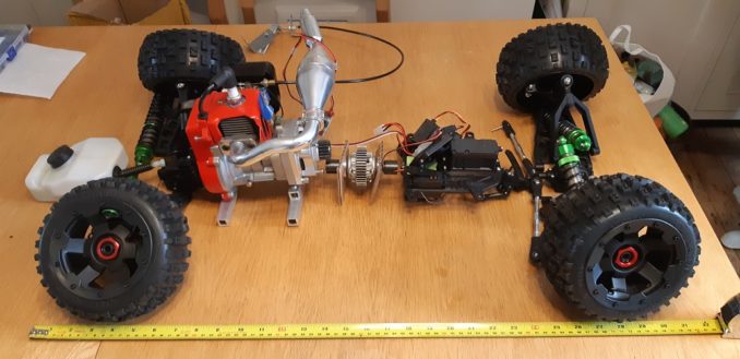
Front assembly:
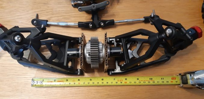
Here I am using the big central diff instead of the weedy ones I currently have. I need to future proof the design if I need to swap this part out for a beefier one.
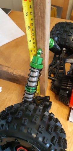
Rear shocks:
For now, back to FreeCAD to mock up what the chassis should look like, as I resume my favourite project pastime, waiting.
Comments, suggestions and advice appreciated; these take about an hour to two hours to write so some feedback to fuel my ego is most helpful for Cnuteneering 11.
Awaiting delivery
Grinder jig
Braising rods
1.25mod gear
Still to be designed
Reverse gear
Actual gear changer
Drive shafts from central diff to front / rear diffs and from front / rear diffs to wheels.
The chassis itself
Pics, vids, words and music © El Cnutador 2020
The Goodnight Vienna Audio file