
Welcome back to Cnuteneering, where the possible is made more difficult by bone headed ignorance, overenthusiasm and pointy metal things being brought at speed close to my fingers.
You may want to refresh your memory on the project in:
Part One.
Part Two.
Part Three.
Part Four.
Part Five.
Part Six.
Design goals:
Fast as possible on offroad; too big to have on roads. I will set a target speed of 50mph.
4 WD.
Must be able to reverse, and brake.
Unbreakable, or as close to.
Must be able to mount GoPro or similar camera on it.
Cheap as possible.
We left last episode of Cnuteneering with the Pinion Of Non Arrival still not arrived. On resending, it did indeed arrive in a reasonable time so that major blocker has now been resolved.
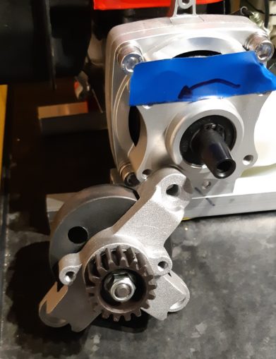
In the above pic you can see the motor, clutch bell carrier (with stylish blue insulating tape reminding me which way the spindle turns when the motor runs) attached to the motor at the top right. The clutch bell spindle is poking out.
To the bottom left is the new clutch bell, clutch bell carrier and pinion all put together, which is how it arrived. The carrier that is attached to the motor looks like it gives much better protection to the motor than the new one, so I though it an easy job to just undo the nut, swap the clutch bells over and away we go.
Nope, the factory in Chy-Na had threadlocked the nut tighter than a socialist at the bar. Added in that I could not be sure if the bolt was “normal” as in clockwise to tighten or “reverse” (as the spindle thread is – anticlockwise to tighten). Luckily the combined wisdom of our puffin engineers BrainDirt and thinktheunthinkableuk (I think that is right, if not ding me in the comments I will not read) suggested putting a blowtorch on it.
While digging out the blowtorch I remembered I had a paint stripping hot gun which I though I would try first.

I kept the heat ray on the thread for as long as I dared, then tried to undo the nut anticlockwise. It budged, just a little, so I knew it was a regular orientated thread. Some more judicious heat ray was applied and eventually, I had pulled the nut off. Threadlock all the way down the entire shaft of the thread. /shakes fist in Chy-Nese.
At this point in time, all my blockers are gone and I can start some proper bloody Cnuteneering! The engine is nicely mounted on some ally box section lengths, the ends of which I can bolt / weld on to the main chassis.
Luckily as I was rooting about my shed of powah looking for the blowtorch, I came across some old synthetic roof tiles. I have no idea what they are made of but they are not too brittle and seemed quite machinable. I also had a stack of about 10 of them so it seemed a good idea to use them as a free prototyping material instead of the polycarbonate. Cardboard just isn’t going to cut it anymore; I need something strong enough to support the weight of the gears.
Back to my trusty 3D model of the gear layout and it is probable that I have made it too short. I need to have clearance under the engine from the front / read differential gear to pass the driveshaft that goes to the rear wheels.
Here I am using another bit of cardboard to get a feel for how big the gearbox plates actually need to be.

You can see the spindle from the engine poking through the cardboard, and the holes I made that match where the mounting points are on the clutch carrier.
Now, the clutch carrier has a circular protuberance of about 34 mm in diameter and I do not possess a drill bit that size. So I had to mark a circle around the spindle, and then drill a series of small bore holes around it to make a circle which I could then punch out and file the rest of it down with the side of a spinning drill bit. Not as neat a job as I would have liked, you can see where the tile has flaked around the big hole a bit.
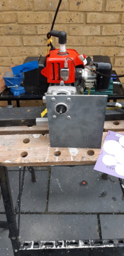
Tellingly you can also see where I had to drill out the hole I had originally made so that it married up properly with the threaded hole on the clutch carrier.
Another reminder to myself to be a whole load more accurate with my drilling and measuring, metal does not forgive errors.
Still, the backplate is now cut and fitted to the engine block and it is mostly straight and level. I can now measure just how far away from the spindle I need to arrange things so that the driveshafts are at the correct level.
In the pic below I have already marked the centre of the first spur gear that meshes to the pinion, all around the large hole where the clutch carrier protrudes. As long as the spur gear is centred on this I am good to go.
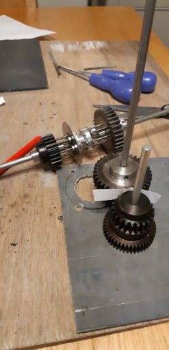
You can also see the other gears that mesh on the second axle, in the picture foreground. I am using a strip of paper between the gears to give them just a little offset from each other so that they mesh nicely and so won’t wear each other out overly when they are in motion.
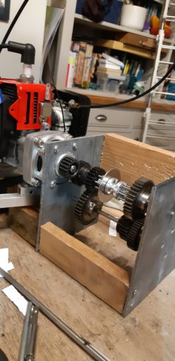
And here we have it, a completed gearbox.
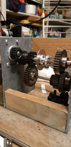
Held together with a couple of lengths of that’ll-come-in-handy wood from the Shed of Powah. Astute eagle eyed readers will note that I have moved the gear change mechanism, the sliding hubs, to the top axle. Rotational force comes from the pinion, to the first fixed gear that is up against the backplate.
Following the axle to the foreground, there is the first mechanical advantage gear (present, but freewheeling on the axle), the Sliding Hub With Giant Washer arrangement, then the next gear which is also free to move. The Sliding Hub With Giant Washer parts will rotate with the shaft, but can move left and right to engage with the gears which I still need to drill holes into to accept the dog teeth.
The second axle has the two mechanical advantage gears attached to it, as well as the drive gear that feeds the front / rear differential gear (which looks like a big black blob at the bottom). I had originally planned for this gear to be attached as part of the gearbox but now I am not too sure. It might be better to have this gear mounted on the chassis itself so if I need to replace it with a bigger, stronger one, I can do so reasonably easily without having to re-make the whole gearbox from scratch.
Overall, I am quite chuffed with the way it hangs together but now that I have something tangible in my hands, rather than some idle pipe dreams and bits of cardboard, I am convinced that the Sliding Hub With Giant Washer is a non starter. Those two little grub screws barely touching the flat part of the D shaft are not going to take the kind of load that these gears are going to put in its way.
In addition to this the gearbox is 160mm long which is a lot of wasted space front to back. Just under a half of this is taken up by the Sliding Hub With Giant Washer arrangement, the collars to keep the freewheeling gears from sliding as the dog teeth are disengaged are too wide.

Just even moving the gears there is a bit of force required – at the minute the shafts are just in 6mm holes in the backplate / frontplate and I do have bearings to mount when I do the final build in aluminium but for now there is just metal on raw… Whatever these roof slates are made of.
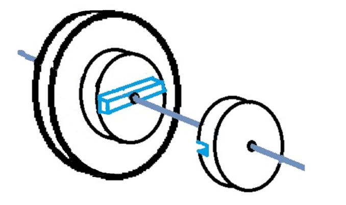
I still like the idea of a sliding hub but I think it can be done better than this. Looking through the vast array of links I have amassed so far my eye lit upon some hex bore hubs, and hex bar. Even better, the hex bar is predrilled to 5mm – the drive shafts are 6mm so this is eminently doable. Quite hard to mess up drilling out the bore hole by 1mm.
This means I can get a short section of hollow hex bar, and attach it to the driveshaft with pretty much as many grubscrews as I like. Hex bore hobs can slide down that and if I get bigger ones than the little ones you see in these pictures, I might be able to cut a groove in one of the hub shoulders, and grind down the facing spur gear shoulder to leave a tongue sticking out that will slot in. This would get rid of the bolts I am using as dog teeth, and reduce the whole length of the mechanism to about 30mm.
To keep weight down I think I will just have the front and rear plates as aluminium (about 360g per sheet!), with tubes running parallel to the shafts. This is driven by the weight of the gearbox – we are at 1.1 Kg already and that is not including bolts to hold it together nor the gear changer mechanism.
As I am also trying to work in a UK supply chain (and I am getting bloody impatient, John) I ordered the parts on Sunday, and they were delivered the following Thursday.
So I can just machine it just so:
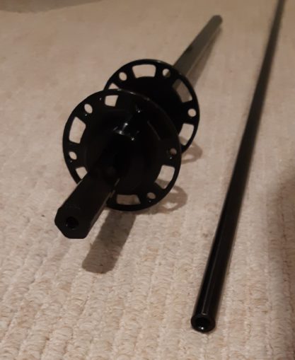
In the meantime this arrived:
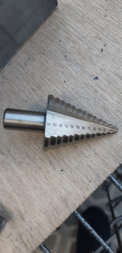
This is not one of RP’s #FF toys, it is a step drill that has both 35mm and 15mm steps that it will cut – I can now cut the hole in the backplate for the clutch carrier, and also the correct hole sizes for the bearings that will carry the shafts.
It is all coming together nicely now! Front and back plate as aluminium, the Black Rod to be sawn to 4 identical lengths to hold the front and back plates together with some 5mm threaded bar.
My mate with the CNC, milling machine and 3d printer has returned from Brahil, completed his 2 week self isolation and then Boris the Cnut puts us all into Tier 4. So that is fucked for the foreseeable then. I could of course, jump over his fence and meet him in his back garden shed where the machinery lives, hmmm.
Looking at the available space now in the gearbox, I have cut a little piece of the hex bar off, drilled and tapped with 4mm holes and swapped it out for the Sliding Hub With Giant Washer arrangement, which now seems much, much sturdier. Dixie suggested bonding the two hubs together to make the gear selector simpler, so m4d pr0ps to him/her for the idea. With all of these changes now in place I have cut off about 30mm off the length of the gearbox, and if I move the drive gear that feeds the central diff so that it is under the hubs, I can probably save another 20-30 mm.
One thing is for sure – that drill press is a pice of junk. The bench mount bends at the slightest pressure so that is a £12.49 wasted. I do wonder if I can stiffen it somehow.
I had better hold off on cutting the chassis box section for a time longer as yet, and as we proved previously, the width of the car is going to be a function of it’s length so I can’t do the suspension arms and hence driveshafts just yet either.
One thing that did crop up here though is that my understanding of sideways moment is faulty. On the Sliding Hub With Giant Washer arrangement, I could push just one edge of the Giant Washer, and the whole hub would slide. Now that the hub is bigger, there is something about the angling that is causing the hubs to bind and refuse to move.
I thought it was a little bit of the grub screws in the hex pipe that were pushing out so I filed them down flush but it was clear that pushing the hubs that far away from their point of contact was a problem. Push the whole hub from each side and it still slides along like butter.
So the gear change actuator is going to have to be much more linear, and the guides are going to have to cover much more of the hub in order to move it.
This is not an insurmountable problem though and I am glad I have identified it now before any other bits of material are cut. As the locus of travel for the gear actuator is now about 30mm, the actuator mechanism is going to have to be redesigned too – it currently describes an arc which is fine when BC linkage is around 50mm, not so much as we get smaller.
It would also be nice to have a resting point in between gears too, so if the car is still being carried by momentum, the car would be out of gear. At the minute it is 1st gear or 2nd, no in between state.
That is also something to be thinking of for the next making it up as I go along design phase.
To finish, here is the video of the gears in motion, you may now ignore the article and shitpost on random topics. I do skim the comments for useful suggestions and questions as I go though.
Still to be designed
Main chassis frame
Rack and pinion for gearbox servo?
Rack and pinion for steering servo?
Suspension arms
Brakes / reverse gear
Still needed
Servos x – one weakish perhaps <10kg? for gear select
Servo saver for steering – this breaks cheaply when you crash instead of the expensive servo gears.
Drive shafts from central diff to front / rear diffs and from front / rear diffs to wheels.
Pics, vids, words and music © El Cnutador 2020
The Goodnight Vienna Audio file


