
Welcome back to Cnuteneering, where the possible is made more difficult by bone headed ignorance, overenthusiasm and pointy metal things being brought together.
You may want to refresh your memory on the project in:
Part One.
Part Two.
Part Three.
Design goals:
Fast as possible on offroad; too big to have on roads. I will set a target speed of 50mph.
4 WD.
Must be able to reverse, and brake.
Unbreakable, or as close to.
Must be able to mount GoPro or similar camera on it.
Cheap as possible.
Very little actual building has been going on so far, just sourcing what I need.
Bolts, wheel nuts, axles, centre diff arrived. Front and rear diffs arrive!
More importantly, the Ten Pound Tachometer has landed.
As regular non readers will recall, I have a spanky spreadsheet of powah to calculate the RPM throughout the gear train, from engine to wheels. I can measure and specify everything now I have the wheels and the gear differentials, but all this is for naught if I don’t known how fast the engine spins at to start with. The engine appears to come in 8k and 12k RPM variants, and no way of telling which I have.
First I have to build my throttle mechanism as I really do not want my fingers close to the spinning shafts. It will also give me some idea how hard I need to pull in order to rev the engine, which will come in handy when I get the servo specified and sourced.
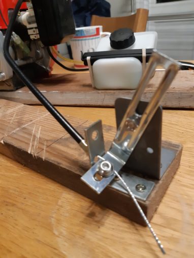
The tacho appears to need a strip of reflective material attaching to the piece to be measured as it rotates (included with the tacho), which I did, only to get meaningless readings.
A bit of black insulating tape over the washer I am using as a makeshift pinion gear and I was ready to measure:
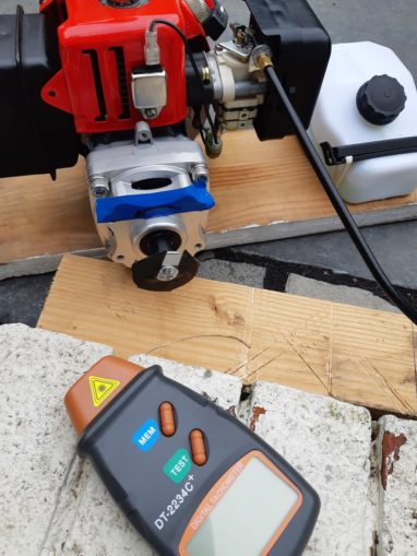
I took a total of 9 measurements, but this one is indicative:
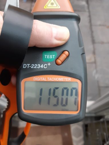
Result! Faster than I had expected, a little off the 12K but I have no idea how much this engine has been thrashed.
So now I can be calculating of the ratios for wheel speed, based on numbers not whataboutery. Kids love the rich taste of science!
At this point though I am not in receipt of the front and rear differentials, which will have a final bearing on the wheel output speed. A friend has a 3d printer I can use but he needs the models to be able to print what I might need.
After a few hours of mucking about, I finally get to the point where I can design a 3d printable gear. Autodesk Fusion 360 is now free for non-commercial use and is something of an industry standard.
The learning curve is fierce but eventually I managed to get a workable gear designed:
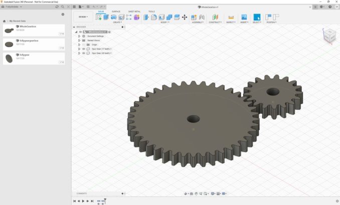
In order to get them to rotate together requires binding each tooth of each gear together so at this point I gave up; I have the 3d files I need so off to my Brazilian mate who has a 3d printer.
Before he can print, the front and rear diffs arrive, so I can actually get on and finish the gearbox design.
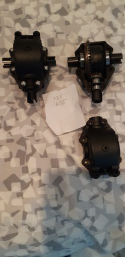
The above is a complete diff on the left – drive from the gearbox runs central, and each wheel is driven by the connectors on the left. On the right, you can see the pinion and spur gear with bearings either side. So it is T shaped if you were to draw out the connections from above. Even better, the slave spur gear can be moved to the other side to reverse the direction of the output, which was a worry for me before the gears arrived.
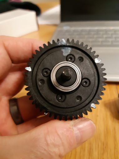
The central diff works a little diff-erently (hah):
The main spur gear is mounted to a housing which holds the differential gears themselves which turn the driveshaft you see pictured here.
One of the things that makes building from scratch so much harder is that so many parts are sold online as “fits model X” and no other specs, like dimensions, weights, thread pitch etc. Even the number of teeth on a gear that “fits HPI Baja Buggy”.
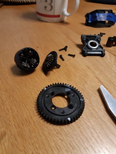
This is the central differential, taken apart so you can see how it fits together. Lots of bevelled gears that give an outlet to resistance forces. If you rotate one side of the drive shafts clockwise, the other drive shaft will rotate counter-clockwise. Handy when you are dead stuck in a ditch.
So now, finally, I can calculate all those gear measurements and ratios:
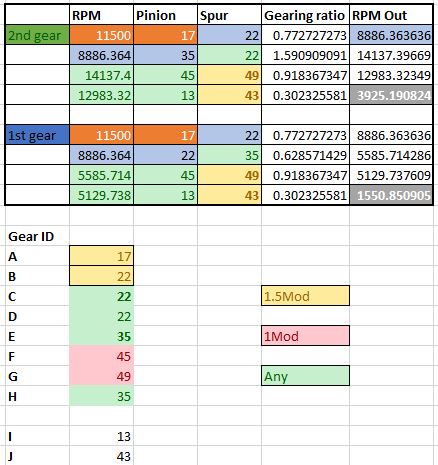
Astute non readers will note that the central diff only needs applying as a ratio with regards the main gear itself; the axles leading to the front and rear wheels will spin at this speed, favouring front or rear over the other if impeded so as not to stress the gear train overly.
The gearing is as such:
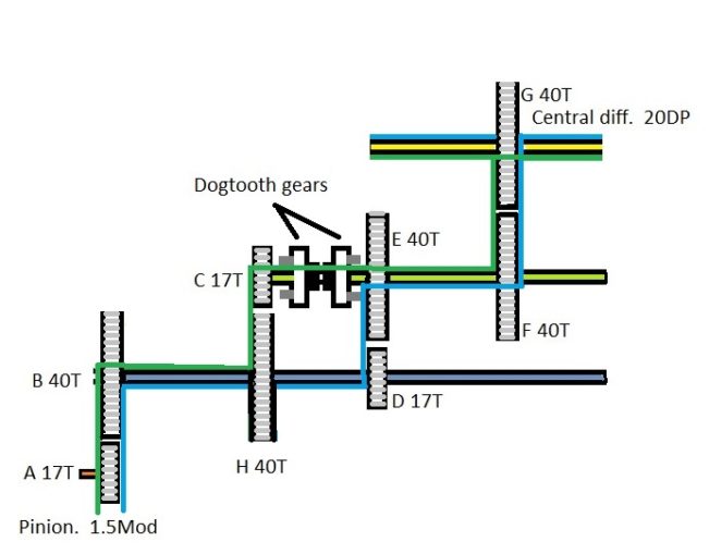
The two new gears, I and J are the front / rear diff pinion and spur, respectively and are not shown on the gearbox drawing but are included in the spreadsheet calc.
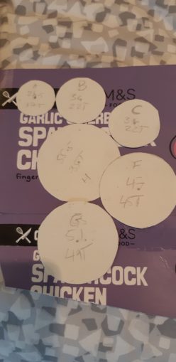
I can now order gears! At this point I really wanted to use a UK or Western company for the gears. However, for a 6mm bore gear we are looking at more than 30 quid for a single gear. I can get one from Chy-Na for less than £8. We progress with a heavy heart but a fuller wallet. Arguably I should support UK business, and delivery will certainly be swifter but across 8 gears that difference is just too huge. Blame the government.
Unfortunately the gears I originally had in mind cannot be sourced in that bore diameter, tooth density (Mod / DP) and tooth count. Luckily, I have a handy calculator so I can swap gear tooth counts around at will to relate what I can buy with what I need to produce the output RPM I need.
Now that the gears are ordered, it is time to work out how I am going to house them. Using my state of the art 3d modelling tools, I can put together a reasonable idea of how they will fit together:
This does not take account of the Z order of gear placement so a little overlap is OK in some places, like F and H gears. Each gear is labelled with the identifying letter, the diameter in mm and the number of teeth. I had to use a compass as printing circles to a specified size when printed is beyond me.
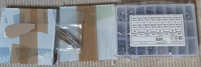
I will need some aluminium plate and I think 15x15cm at 6mm thick should do, based on the model above. 6mm seems to be a common bearing width and that is the size of bearings I have. I think some polycarbonate sheeting will be handy to make a properly working prototype of the gearbox so I can see what is going on. It is loads cheaper than aluminium so I will make my mistakes there. Plus having some polycarbonate sheeting kicking about might come in handy for battery / servo mounts later.
This time I was able to source from UK sources and the PC and ally sheet arrived toot sweet. Plus some taps to make threads in the ally and PC sheets too. The place I bought the aluminium had a minimum spend so I picked up aluminium box section there at a reasonable price. I think my dreams of a MIG welder and steel chassis are quite likely gone now, aluminium is a bastard to weld unless you have specialist / expensive kit. Which is a bit of a disappointment as MIG welding is +10 ManStuff. On the plus side aluminium is easier to machine though, so any drill bits / taps / saws etc will take a lesser beating.
Now, I can finally get building. Here we have the Mk1 Gear Changer, gears are labelled as per gearing diagram above.
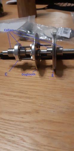
Gears C and E are freewheeling on the axle, constantly driven by their respective gears (H and D), and stopped from sliding up and down the shaft by the collars. At the minute C and E are a spare hub and some washers as I wait for the gears to arrive, but you get the idea.
When a gear is selected by moving the dogtooth left or right, the bolts in the dog tooth gear engage into holes in the gear to rotate the axle at the same speed as the driving gear. Remember, the dog tooth gear rotates with the axle but can slide up and down it, pushed by the gear selector.
That is the theory, anyway. At the minute, the bolts are too long and too thin I think to sustain any reasonable torque. If I can find a way of shortening the width of the collars that’d be useful, perhaps cutting a thin groove into the axle and pushing a C clip in. The gears themselves will not really take much sideways load, beyond being jostled about when the car is going over rough terrain. But, we shall see.
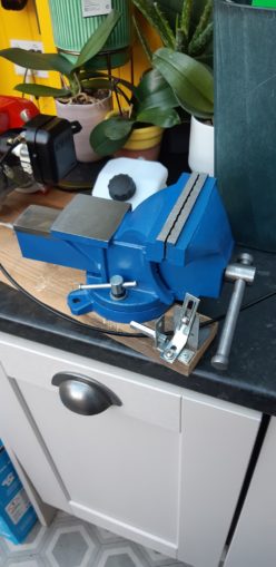
Now that I have some actual hardware I need to cut / drill, I need something a bit more substantial than getting my daughter to hold material as I drill or saw it. Yay, #ManTools! (I hope SB does not post this on an #FF).
Looking ahead, I now need to start thinking about the chassis and how that is going to look, and work. The main ticket items are really the engine and the gearbox as these are going to be the heaviest parts of the car. So I need to think about how wide the car is going to be in relation to how long it is. Wider is more stable, but will have impact on steering mismatch between outer and inner tyres (imagine the difference between the circles that the inner tyre and the outer tyre will track when going around a 90 degree corner), and probably put more stress on the steering servo.
From https://www.rovanrc.com/product-rv360sltv5r:
This Buggy is pretty big at 32 inches long, 20 1/2 inches wide, 12 inches tall and weights 32 pounds!

Its short 21 3/4 in wheelbase and wide 20 inch track
So that gives me something to aim for I reckon. The shorter I can make the gearbox the better but I am going to have to hold off deciding the length of the car until the gearbox and steering are finalised. I do need a better engine mount so I can attach the gearbox to it though, a bit of scrap wood is not going to cut it for much longer. The driveshafts will have to pass under the engine though so that is a concern if it pushes the centre of gravity too high as the car will be prone to rolling when cornering.
Right now I need to borrow my Brazilian mate’s milling machine to cut some holes and material, but he is unfortunately called back to Rio for an ailing parent. This means I will need to get a drill press to ensure my holes are perfectly orthogonal; one thing I have learned so far in metalworking is that there is _no_ forgiveness if you are out by a fraction of a millimetre.
Still to be designed:
Rack and pinion for gearbox servo?
Rack and pinion for steering servo?
Suspension arms and wheel mounts
Still waiting for:
Pinion gear clutch bell 16th Nov should have been here between Oct 27 – Nov 16. This is late you bastards!
Still needed:
Pinion gear clutch bell should have been here between Oct 27 – Nov 16. This is late you bastards!
Servos x 3, one powerful, one reasonable, one weakish
Steering 60-65kg but 45kg is stock for most 1/5 cars
25-30kg throttle
<10kg? for gear select
Servo saver for steering – this breaks cheaply when you crash instead of the expensive servo gears.
Shock absorbers.
Drive shafts from central diff to front / rear diffs and from front / rear diffs to wheels.
Pics, words and music © El Cnutador 2020
The Goodnight Vienna Audio file


