Welcome back to Cnuteneering, where the possible is made more difficult by bone headed ignorance, overenthusiasm and pointy metal things being brought together.
You may want to refresh your memory on the project in:
Design goals:
Fast as possible on offroad; too big to have on roads. I will set a target speed of 50mph.
4 WD.
Must be able to reverse, and brake.
Unbreakable, or as close to.
Must be able to mount GoPro or similar camera on it.
Cheap as possible.
We left the last episode of Cnuteneering with teething problems of the gear changer. WARNING: post contains spaniel.
The previous pivoting mechanism was suffering from friction, which was galling.
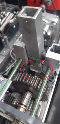
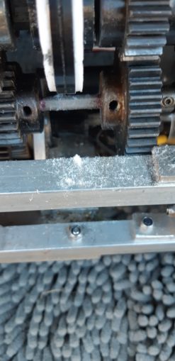
In the red circle you can see the gear selector is overheated, eaten and bent. Some may say this was an excellent #FF but this is Cnuteneering. I can use the (unusually for Cnuteneering) perfectly parallel M5 studs as a guide track for a replacement mechanism. The line of the studs is the green lines in the pic above.
I still have some 5mm inside diameter tubing that fits the studs nicely and will slide. I do think that having 2 slides is not going to be a good idea as I can’t guarantee the force will be pushing parallel – the servo horn describes an arc as it moves, not a straight line and putting a rack and pinion in is going to be costly. So I think a loose rider on one side will do the job, something like this:
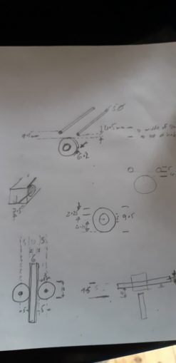
That at least gives me a starting point. I think rollers made of PTFE could work in the mechanism, which is what the FreeCAD drawing below shows.
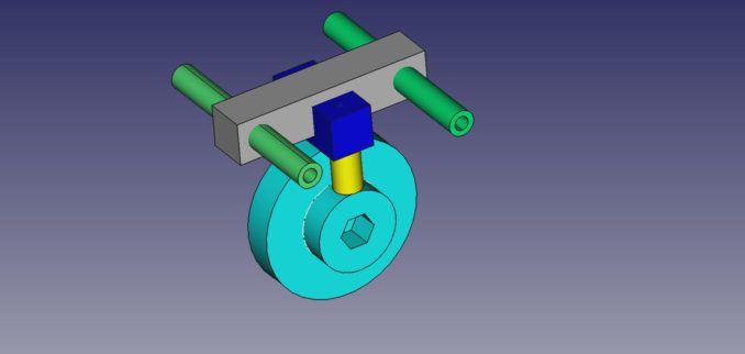
In the above, I think the green tubes only need to be on one side, the other side can just be a channel cut to slide on a tube that covers the threads on the stud like a sleeve. There should not be too much friction there and it will still work OK. I think!
While flights on fancy on a computer screen are useful to view conceptually how the mechanism is to work, it is a far cry from the reality. There is not an awful lot of space in that part of the gearbox, because I did not want too much weight high on the car.
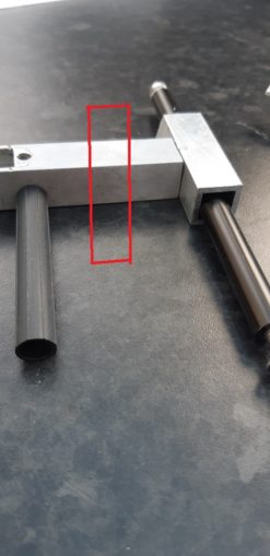
Measurements were taken and drawings made.
So now I think I have an idea of how the new gearchanger will look. If I was to use a bit of aluminium box section as the cross piece, it would foul the gear hub which would be bad. I could cut it down but that will massively weaken it. What I need is a bit of plate metal that I can use, so off to the offcuts bin to look for one, otherwise I will have to cut down a piece of 150x150x6 plate which I am trying to save for if I need to rebuild the gearbox front and rear.
Luckily I find a piece that is almost perfectly sized, which is a most excellent result. There must be a word for that in Cherman I am sure, metallgefinden or something I would imagine.
The main problem is friction, so I think if I use PTFE points of contact I can get around this in the changing mechanism. Accordingly, I am off to ebay for some further investment.
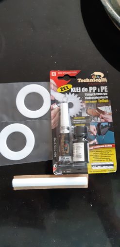
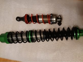
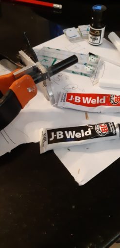
I have two PTFE thrust washers, a short length of 10mm rod and some special glue. PTFE is very, very slippery to touch and most regular glues will not bind to it which is something of a problem. So this specialist glue comes in 2 parts, a primer to make a PTFE surface more glue-able and a superglue derivative that will bind it to most things, including metal.
I do realise though that the washers are going to be hard to fit as I will have to disassemble the gearbox one more time to fit them to the hub. Luckily the friction from the current gearchanger has nicely abraded the aluminium hub, so I think if I just cut a line across the washer I can just slide it in place without having to spend a whole day taking the gearbox apart then putting it back together again. That would be about a whole day and a heat ray gun involved so I’d rather not urn that time if I can fast track the work.
Making rollers from the PTFE rod is going to be tough going as I don’t really have the means to hand to drill a 3mm hole perfectly central. If I am out by even a fraction of a millimetre the roller will become an ovoid, and bind in one spot before wearing. Mounting such a roller would also pose a challenge, so for now I just cut a short little length off to make a PTFE button which I will use as a pad to push against the thrust washer. And once again, a wing and a prayer. I think if the PTFE button wears down I can always replace it fairly easily as the gear changer is quite quick to remove – 2 nuts and one bolt and it comes away easily.
The thrust washers went on reasonably easily, although I did chamfer the edges a little too much where I put the slit in the edge to get them over the axle. Exciting times as I am used to working with the 60 second glue which gives you a fair bit of time to get your fingers clear before it sets, not so much this stuff. Some tense moments pulling my fingers off as I bedded it in. I just had a mental picture of me arriving at A&E with a 16Kg radio control car attached to my hand and having to explain myself.
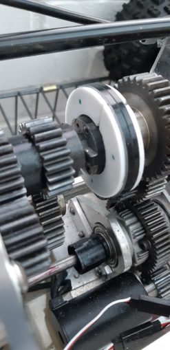
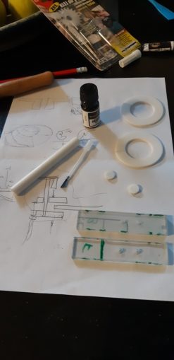
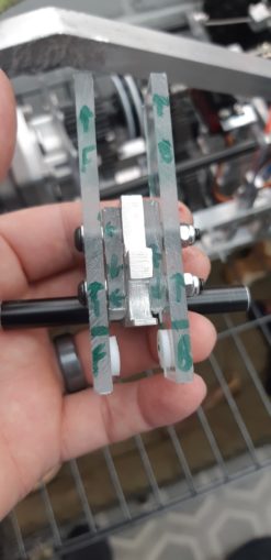
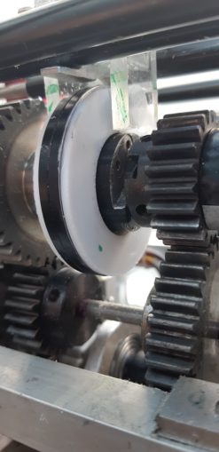
Everything fits nicely, so I am quite pleased with this so far. The green dots on the PTFE are to show me which side is not to be glued – the glue is transparent and the washers have a little burr around them which I wanted facing out rather than in.
While that glue is setting, I cut the bit of aluminium up a bit, putting a notch on one side and a hole on the other, plus an arc taken out of one side so it does not hit the hub as it moves. My new best friend, JB Weld, is bloody awful stuff to have on your hands but it does glue aluminium together very, very well. There is a little wobble of the tube in the housing, so I use a bit of angle aluminium to clamp the tube and the plate at exactly 90 degrees.
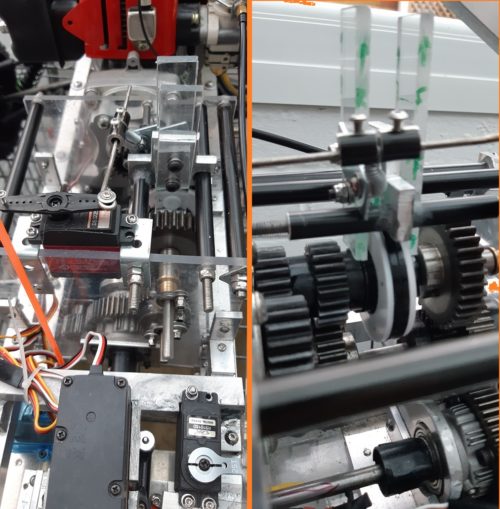
In the photo above you can see the polycarbonate guides with the little PTFE buttons I cut with The Sharpest Knife In The World, also with the handy green “don’t glue this side” markers. I leave everything to set overnight.
I can now make a couple of extra spacers out of polycarbonate, add a couple of washers and the clearance is about 1-2 mm either side between the PTFE button pads and the thrust washers. Standard FRONT and BACK and UP markings on the polycarbonate to prevent Mr Fuckup visiting when assembling stuff. I hope the polycarbonate will be strong enough to move the gears; it seems sturdy enough when I bend it but it also has a little give in it which is great for this situation. I use the Nyloc nuts again as experience shows that ordinary nuts won’t make the nut and will fall off inside 2 minutes.
Fitting it is very easy, just guide the pipe along the m5 stud that runs the length of the gearbox. A couple of springs (200) from the big box of springs and I can reuse the push rod that attaches to the servo, and we are able to test operation.
Not bad. Now I just need to take it outside out to my luxury fully appointed workshop to run some operational tests with the engine running and the wheels jacked up, but instead the Gods of Cnuteneering decide to send a pissing down rainshower instead. Hurray for Global Warming! As an aside – if ivermectin ever gets mass approval for C19, would that then be Global Worming?
One thing is bothering me still and that is the braking. It is nowhere near as strong or as quick as I’d like it to be. Unfortunately, the motor I use for braking is controlled by the throttle on the Tx – if I add a mechanical aspect to it then the mechanical brake will still be engaged when the motor is trying to go from braking to reverse, which will be a massive fail and expensive as the motor and ESC burn out.
I need the mechanical brake to be engaged for 0-75% of the Tx trigger, then to release so that the motor can reverse the car.
I uhm and aaah about it for some time, can I do this electrically? Some kind of solenoid, PWM threshold circuit?
Eventually I come up with this idea which is still in development.
The green rack gear is obviously supported, and is pulled away from the yellow gear at about 75% of full reverse on the Tx throttle. Until then, it exerts a pull on the red flap, which will connect to the cable that goes to brake callipers, similar to those found on a bicycle. The grey spring will pull the assembly back together when braking is done, and a one way bearing in the yellow gear to blue shaft means that the assembly can put itself back together again after braking stops.
The mechanical brakes are only engaged up to a point then the assembly no longer transmits force so the reverse gear can kick in. The central diff will push all the braking force from the motor through to the front diff.
More thought required on this anyway.
I take a much needed day off work as I have been pretty stressed of late, new job, moving house and all the C19 bollocks. The day dawns and I am ready to go, as for once is the weather. My test site has the road rammed with uber minicabs which is annoying as I wanted the actual road not the offroad to myself. No matter.
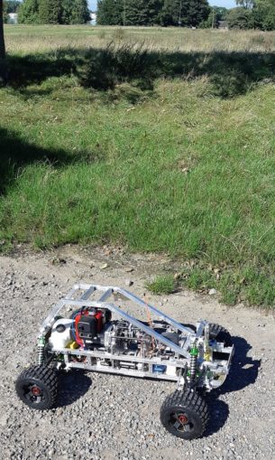
And here we have it, the first sustained full throttle run out in 1st gear:
Nothing seems to have fallen off or come loose, which is a first.
This is actually fluffy seed pods from the field, and not shredded PTFE as I originally feared.
There seems to be a little wear and tear on the mechanism – all but one of the “this side no glue” markers has been rubbed off
But, for a run out it was pretty good going, I actually got some full throttle running in.
It is the end of times, the wolf shall lay down with the lamb.

So now, to attach the TelePi and get some real, proper readings out of proceedings. Then fit the shiny airfilter, race exhaust, and then finally put a bodyshell on it. I still have _no_ idea how fast the Cnutmobile is going, but sooooon….
Still waiting for:
Nothing!
Still left to do / think about
End point adjustment for servos and control mechanisms Dumbo RC setup
Siting of RPM counters
Body shell
Pics, vids, words and music © El Cnutador 2021