
Welcome back to Cnuteneering, where the possible is made more difficult by bone headed ignorance, overenthusiasm and pointy metal things being brought together.
You may want to refresh your memory on the project in:
Part One.
Part Two.
Part Three.
Part Four.
Part Five.
Part Six.
Part Seven.
Part Eight.
Part Nine.
Part Ten.
Part Eleven.
Design goals:
Fast as possible on offroad; too big to have on roads. I will set a target speed of 50mph.
4 WD.
Must be able to reverse, and brake.
Unbreakable, or as close to.
Must be able to mount GoPro or similar camera on it.
Cheap as possible.
We left the last episode of Cnuteneering at the beginning of actual construction, with yet another fail chalked up as my gas torch seemed to have died somehow. The new torch arrived and it was straight out to the machine shop back patio to do some brazing.
I should point out that I program computers for an investment bank, I have no formal training in engineering whatsoever. This is becoming painfully obvious the more puffins that do know what they’re doing offer their advice and assistance, so thanks for that my fraterculan amigos.
Everyday is a learning day when you’re Cnuteneering!
I clamped everything up for the braze on my state of the art brazing bench, and set to work. After a few tries, the solder did not melt on the heated aluminium as I had seen on the YouTube instruction videos. It was cold out, but also quite bright and I could not see where the hot point of the flame was to focus that on the metal.
This is what the flame coming out of the torch looks like. The red arrow points to the hottest point of the flame.

In this light it is really hard to see where the hot point of the flame is so I waited until late afternoon and tried again. This meant I could see where the hotpoint of the flame is and also – the hue of the metal changes as it gets hotter. Channeling my inner Hephaestus, I still could not get the aluminium hot enough to melt the solder directly. What I did find out was that at a certain hue of aluminium, a quick blast of the gas torch on the solder was enough to melt it onto the aluminium channel. It is however something of an art.
There was some lumpiness though, melted too much solder with the torch.
And then this is what happens if the torch is held too close to the hot metal
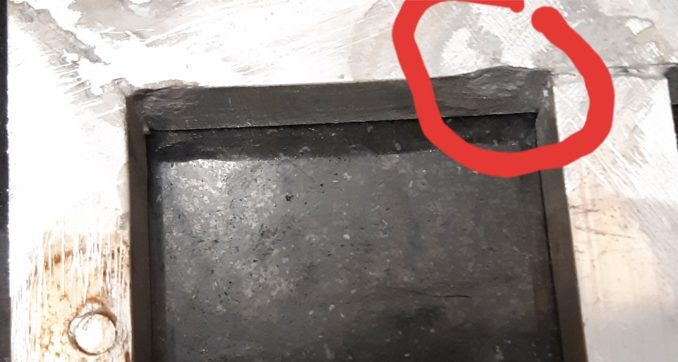
The force of the gas from the torch was enough to put a dent in the aluminium which was quite the learning experience. You will also see that I did not clamp the aluminium in place for this one though and the joint moved just when it was hot enough and ready. Valuable learning experience- aluminium conducts heat very well and cannot be moved with a bare hand for some time after brazing. No tealights required though.
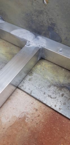
There was a little bit of filing down needed but the joints cleaned up OK. The dent and rust was from the G clamp I used to hold it in place.

I learned a lot from this test firing, not least to go easy on the filing of edges to make a channel as the two pieces line up – more like 60 degrees than 45.
Given that the solder had to be assisted in melting I am not sure if these are full strength welds or not. The chassis cage needs to be strong, if when I crash, it needs to withstand the impact and not break.
Back to A level physics then where I recall:
F=ma
Force = mass times acceleration
And
PE = mgh
Potential energy = mass x gravitational constant x height of object above ground
Neither of which are particularly useful to me as I am likely not going to be accelerating upon impact, more like cursing the corner I cut when making the brake mechanisms.
In real life, this is how it works.
It will be KE=1/2mv^2 happening when I slam head first into a brick wall or steel railing.
Kinetic Energy = ½ mass x velocity squared.
At this point I just gave up; there is no way of knowing how the impact is going to be angled at the car so let’s just do some Cnutscience instead.
There is about 5.1 Kg in the bag:
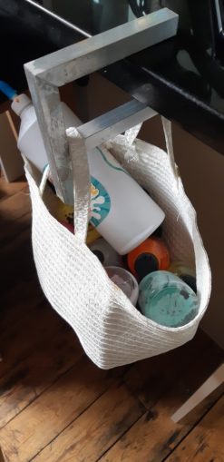
Passed with flying colours!
And try as I might, I cannot squeeze hard enough to break or bend anything on the test piece with my soft office worker’s hands and weak nerd arms.
Instead, I just dropped a brick on it. The brick is 2.25 Kg falling 50 cm so it exerts 2.25 * 9.81 x0.5 = 11N of force..
I have no physical understanding of what “11N” means other than “eleven Newtons of force” but this tells me what I need to know:
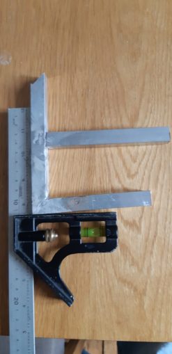
The aluminium bends rather than the weld breaking. Might have weakened it in the heating, but the joints seem strong enough for Cnuteneering. Result!
All of this stressing and strain has had me rethink the driveshaft strategy – at the minute it is 15mm piping and a prayer. Torsion is basically twisting which is almost the same as shearing so I guess that is close enough to use (expecting to be corrected on this).
I looked up the shearing strengths of materials:
this is for hole punching but at least it gives me an idea for comparison.
Aluminium does not do well unless it is of specific alloy – aerospace grade. This can withstand 54K PSI before it breaks.
10mm Dia x 100mm = £6, for 500mm = £17.56. This is arse because I need ~242mm for the front driveshaft and ~296 for the rear; effectively this will cost just over 35 quid.
This is compared to mild steel which has a shear strength of 50K PSI and I can get it 10mm Dia x 500mm for £5.60. A little weaker and much heavier than the aluminium and I can’t weld it. Next up is 40-50 Carbon steel which has a shear strength of 74K PSI but seems hard to buy for a casual Cnuteneer.
Or I could get some fairly reasonably priced HSS steel.
Hmmm. The location of the brakes is a bit tricky as there are too many structural bits around the area if I try to attach them to the drive cups that come out of the centre differential. Being able to put the brake disks anywhere on the driveshafts would be very useful. I will have to shelve this under “Ignore for now as it’s too hard”.
My JIT schedule of Cnuteneering seems to be failing in a Dutchland airport where my goods are held up for no reason. I am stuck engineering wise and I really need to be getting some coding done to rejig El C’s ARSE Raspberry Pi 3 Model B Rev 1.2 project to capture video and GPS info to disk. Reworking the code could take some time as I have to work out how to interface with the GPS service on the Pi and then overlay the text on the video if I can. If that is too hard / not possible I just need to write the info to a file and I can overlay it to video offline later.
I had to set up my Pi with a new, 32 Gb SSD card to have space to store the video files which I shall not bore you with the details of. While rebuilding the ARSE I was having problems linking to the newly updated graphic interface libraries and had to look at the provided example programs to see how they now worked. It looks like a provided application to demo the camera, RaspiVid, now has a GPS module capability! This is both good as I don’t have to do any coding, and bad as I don’t have to do any coding. I quite like tinkering back in my comfort zone where I actually _know_ what I am doing.
A bit of faffing and voila – camera is saving video with GPS info contained in there. It is some really lovely, tight code that does the GPS interfacing, it has been so long since I saw code like that…
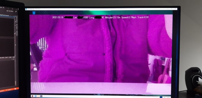
(edited so I don’t self – doxx).
The GPS code has some cacheing of values with a stale flag in there too, about three in every five calls to get GPS info return nothing so the “good” info is cached for a little while and then marked as too old to use. I can probably hijack this code to read other sensors too like temperature and RPM, and put that on the display. Total result! I just need to work out what sensors I need to get. Engine RPM would be good, central driveshaft output RPM would be great. A minute of video camera footage takes up about 100Mb, so with about 18Gb spare to play with I have plenty of storage space.
I need to work out just how to get the Pi into a mobile state; at the minute it is wired in to my network and power and the breadboard that the GPS fits into is just a mess of stuck together wires. A quick search of the internet and I have a 3D printable case for the Pi with attachment lugs, some faffing with FreeCAD and I have from top left, clockwise:

Camera front cover, camera holder, breadboard holder top and breadboard holder bottom. Rendered as STL files and sent off to my Braheelian mate for printing. Physically, the units can now be combined together in a format that can be mounted anywhere but I need to be able to power the unit and tell it to start recording. I can get a little touchscreen for it, or perhaps I can plug it into my laptop and use that screen.
While looking for screens, it turns out that you can set up your phone as a WiFi access point, and get your Pi to use that as its network connection. I tried this and it works! x
Even better – I can install an app, Real VNC, on my phone and remote control my Pi when out of the house and away from any home infrastructure!
Finally – some tangible progress. While waiting for tools from Chy-na and possibly some beefy front / rear diffs. Mmmmm, waiting.

Still left to do / think about
Buy more welding rods
Test cutout switch on plane Rx
Finish Pi cases / breadboard / camera support
Test Pi on battery power away from home network
Get a working cut out switch
End point adjustment for servos and control mechanisms
Petrol tank and centre of gravity
Front suspension arms / driveshaft problem
Test range of VNC connection to Pi
Pics, vids, words and music © El Cnutador 2021
The Goodnight Vienna Audio file


