Welcome back to Cnuteneering, where the possible is made more difficult by bone headed ignorance, overenthusiasm and pointy metal things being brought together.
You may want to refresh your memory on the project in:
Design goals:
Fast as possible on offroad; too big to have on roads. I will set a target speed of 50mph.
4 WD.
Must be able to reverse, and brake.
Unbreakable, or as close to.
Must be able to mount GoPro or similar camera on it.
Cheap as possible.
We left the last episode of Cnuteneering with teething problems of the gearbox, plus some bits falling off the car. In a field. CAUTION: post may contain spaniels.
The Cnutmobile does not seem to want to meet its full potential and I am beginning to worry that I have not done my sums correctly and the pieces of the gearbox are not spinning as fast as they should.
So I need to measure the spinning rates of all the important gears. I could do that with the TelePi, but that will be quite some faff at the minute and I have not yet tested the sensors to see if they are giving accurate readings as yet. I still have the handheld digital tacho though so that’ll do nicely for now. It also means I have the reflective strips mounted on the gears for when I do fit the TelePi properly, so it is all moving in the right direction.
First step is to put the reflective pads on to the gears, as highlighted below:

I am measuring the speed of the drive shaft as measuring the speed of the motor is not possible as I can’t get a reflective pad anywhere that I can position the tacho to read it, this is the far right red circle. The middle is the drive transmission shaft, and then on the far left there is the output to the front differential.
I will have to test and take readings for both first and second gears at full throttle. I prop the car up on bricks, ScouserStyle, and get revving.
The kill switch is still not working so I disconnect it from the ignition circuit for now.
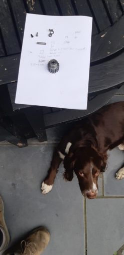
At the end of testing, there is quite a few bolts and nuts on the bench that have shaken out.

And shaken off:

And here they all are gathered into a nice pile. The other lug from the front shaft has also been shaken out, so I replace it with a 4mm bolt that has a nyloc nut so that should keep it together for now.
All the testing is done, so I sweep up the pile of bits for later re-attachment; everything on this car is there for a reason at the minute. GQ did note that this is because I do not have a multi million pound R&D dept to add “bits that are designed to fall off”.
I can now put the test results into my SPREADSHEETOFPOWAH and see how far off I am. Longtime readers will know that I had a last minute fail on buying gears that will fit, and the front and rear diffs offer a 13->43 gear tooth count step down and there’s nothing I can do about this at this time when I had kind of assumed I could get a better ratio than that..
These are the initial calcs, the important info is in the RPM Out column as this shows how the transmission speed varies throught the drive chain.

And here we have the actually measured with a measurer numbers.

They are likely to be a little bit out as I could not reve the engine for too long at max throttle so did not have time for the reading to fully stabilise and given the amount of stuff that has flown off the car so far, I am a bit lairy of having my face that close to an open sided gearbox for too long.
However, I am reasonably confident the readings are within 10% of reality, and that is Close Enough For Cnuteneering.
And here is the tale of the tape, the grey background boxes contain the speed the wheels will spin at.

So it looks like I will just about make the 50mph band, possibly 48 MPH I would think. I am quite pleased by this as at least, in theory, the car should go at just about the target speed. But as we know, all computer generated models must be validated by real world data. Or at least I know, I am just a bloke in a garden with a hacksaw rather than a professor of modelling at a prestigious university. Could do with some of their funding though.
I do attempt to reconnect the kill switch, as I get closer to working out all the little kinks and problems of the Cnutmobile I will be going for a speed test in the near future and there is no way I am going to do that without at least a kill switch to stop the engine dead.
The engine will start, run for about 5 seconds and then die when the engine runs for a bit. Stop It gave me a really good heads up on the possibility of RF interference messing with the signal, so even replacing the cables to the kill switch would not make a difference. I did notice that the kill switch “I AM ACTIVELY STOPPING THE ENGINE” light kept coming on and going off again while I was speed testing though; I wonder if it was somehow generating a backward spike all of its own that was shorting the ignition out.
I resolved to put a break in the comms and power lines to the kill switch so I could put an AVO on it and measure the +ve and –ve lines to the unit. While I was working on how to do that (the comms and power cables are inside a plug which I don’t have spares for, so some faffing would be required in order to not damage the plug while measuring), I made sure the battery was topped up properly.
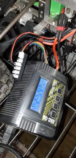
LiPo batteries take 2 feeds when charging – here you can see the red and black main power lead connected to the battery, and the weird white plug thing on the left. This is the cell balancing mechanism – there are 3 separate cells in the battery itself and each is monitored to see how much juice it needs to be fully recharged. Big batteries for your Tesla work a bit like this too.
The problem is that the battery has to be slid out from the underpan on the chassiss which is more faff than it should be (4 bolts, shit design), so I bought a balance extender lead that means I can charge the battery in situ.
Once charged, I take the car back out and get ready to fit the circuit interruptor (sadly no photie but it is basically a lead on each power line that I can attach the AVO to as well as the killswitch itself).
Disconnecting the killswitch, it felt a little wobbly. I parted the plugs, had a look in the guides, and put it back together again. The plug went about 5mm deeper than it had been inserted previously (filth, yes); it has a little more resistance to being fully connected. Pushing it in all the way seems to have cured my killswitch problem, so that is a total result and no mistaking. The engine runs continuously even at high revs without the killswitch kicking in, as it has a reliable connection to the Rx. On the plus side – at least I know it works if the connection to the Rx is dodgy!
I now have to go back and refit all the bits that fell off and make good any damage caused by the run. I can start threadlocking some of the parts now which is good, but one issue is not going to be solved with a blob of cyanoacrylate:

As you can see, the gear selector is getting warmed up and then bent on the collar of the selector hub. It is also getting eaten away, as well.

Grimy Miner’s assessment:
“Changer needs to be Phosphor Bronze, or Brass as an absolute minimum. Also, gears need to be steel, or have a replaceable steel shim washer for the changer to bear on.
The binding up you are experiencing is called “galling” and is because Aluminium is a very soft metal with incredible heat conducting capacity, so that any two aluminium surfaces experiencing friction will cause one or both to attempt to fuse together.
Look at the surfaces that touch, through a magnifying glass, you will see little “bobbles” of metal – that is galling (in more than one sense of the word)
If you need any help in remachining anything, just shout, I want to see this beast hammering down the road as well.”
Was spot on the money and the offer of assistance is gratefully received. The Gods of Cnuteneering smile on me once again, a subject matter expert giving me good, free advice. For now I might need to change the way the gear selector movement works though, so I check my spare aluminium bin for something that will fit. I am down to my last 1.5m of box section so a bit of recycling would be useful.

I try to put a little curve into the part of the gear selector that rubs up against the hub, a cold chisel and little shims under the edges of the contact area.

And a few big whacks later we have:

I am going to need some more pushrods though:
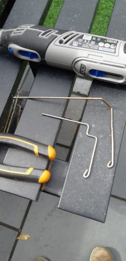
Which now don’t fit so I have this arrangement instead:

The pushrod goes through the selector with compression springs either side, instead of pulling a tension spring as before. Sounds like a great idea, but…
It doesn’t work, the path of the push rod is too curved.
What I need to do now is work out how to stop the aluminium contact points from eating each other. I think I can get a big PTFE washer to glue to the aluminium hub, and then some PTFE rod I can cut a small bit off, put a bolt through it and have some kind of roller mechanism in there instead that will rub up against the PTFE washer on the hub. I may also retry the guided mechanism again – two pipes over the threaded rods that currently hold the gear change pivot, but with a longer section of piping to prevent angular snagging.
So off to EBay to get some more parts, and hopefully some success soonish…
Thanks for all the puffin support in the last few weeks, it has been a great help.
Still waiting for:
Nothing!
Still left to do / think about
End point adjustment for servos and control mechanisms Dumbo RC setup
Siting of RPM counters
Body shell
Pics, vids, words and music © El Cnutador 2021