
Welcome back to Cnuteneering, where the possible is made more difficult by bone headed ignorance, overenthusiasm and pointy metal things being brought together.
You may want to refresh your memory on the project in:
| Part 1. | Part 2. | Part 3. | Part 4. |
| Part 5. | Part 6. | Part 7. | Part 8. |
| Part 9. | Part 10. | Part 11. | Part 12. |
| Part 13. | Part 14. | Part 15. | Part 16. |
| Part 17. | Part 18. | Part 19. | Part 20. |
| Part 21. | Part 22. | Part 23. | Part 24. |
| Part 25. | Part 26. | Part 27. | Part 28. |
| Part 29. | Part 30. | Part 31. |
Design goals:
Fast as possible on offroad; too big to have on roads. I will set a target speed of 50mph.
4 WD.
Must be able to reverse, and brake.
Unbreakable, or as close to.
Must be able to mount GoPro or similar camera on it.
Cheap as possible.
We left the last episode of Cnuteneering with more field tests and logging data, hopefully the last iteration in the design of the gear changer, RPM sensors and front wheel driveshafts falling apart and a loopy spaniel.
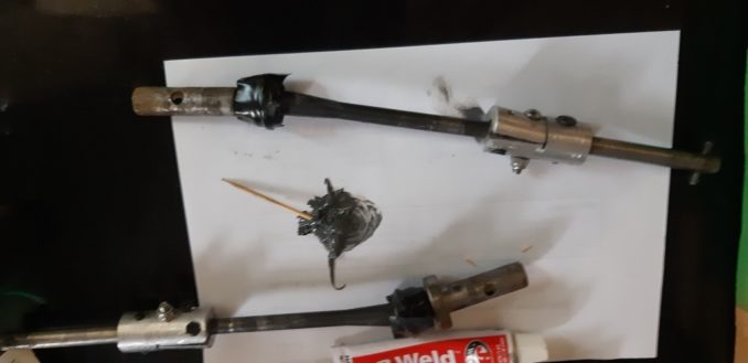
Firstly, let’s sort out the driveshafts. Unfortunately this requires removing the shocks before the wheel in order to get the drive shaft out. Our old friend JB Weld makes an appearance. I cut some thin cable ties to the right length and wrap them around the outside of the socket, firstly to stop glue getting into the hole and also to provide another strong barrier to the cotter pin slipping out. Wrapped in insulating tape to keep the cable tie nicely tight to the socket.
One lesser known trait of insulating tape is that it is quite elastic – if you stretch it when you apply it, it will gradually return to normal size and compress what you’ve wrapped it around. This should hold the strips of cable ties neatly to the shaft hoods.
Left to dry overnight and we’re ready to go again.
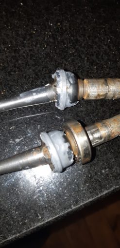
Insulating tape removed and a little bothered by the rust. Some WD40 on that before the parts go back together again.
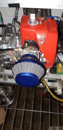
While I am faffing, I fit the shiny new air filter. “Swag” as my daughter would say.
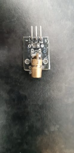
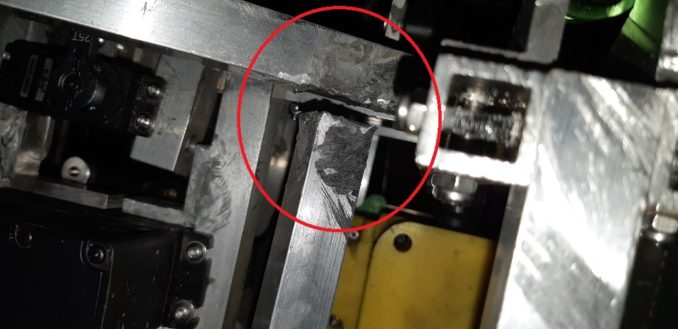
One thing that was clear in the last field test is that the RPM sensors are either not sensing or are a little too variable in working / not working. Taking a closer look I can see why:
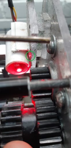
In the green circle you can see the reflected laser beam completely missing the sensor, so no wonder it was not ticking along as the car moves. Observant puffins will note that the laser itself is pointed at an angle, this is how it is bonded to the PCB driver gubbins, and it is not straight.
I pull the laser component out and you can see a bit better what is going on:
As I try to correct it so it points straight ahead, the brass bit falls off the PCB. There are a small amount of tears as I head over to banggood to order some more, but I need to be thinking about how to get these sensors straight and working, and how to keep them there.
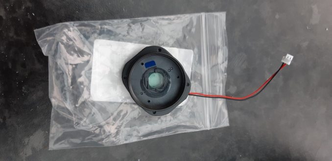
In the meantime I’ve been off on ebay again and looking for filters for the TelePi camera. Astute readers will recall I repurposed the night vision camera from the ARSE project and this is why the footage looks like I am on Mars. Sadly ebay retailers had no handy little 10mm diameter circles of filter glass for pennies apiece but for a few quid I got a switchable filter unit. Apply voltage and it stops filtering.
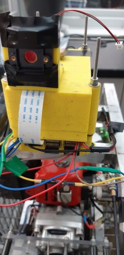
To test it before I make a more permanent fitting I simply tape it to the unit, with the power lead flying free.
And now – the field test!
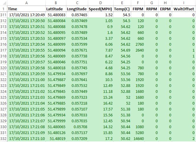
Some lovely stats retrieved but sadly not the rear diff or engine RPM counts
And so, back to the garage for a little cleaning and an assessment of damages. Some cracks are appearing in the mounting plate of the TelePi which is something of a worry. In hindsight I should have made these much beefier.
A period of inactivity followed by a trip to seem my Dad who had fallen off a ladder, cracked his shin in 2 places and picked up a serious infection in the wound to his leg. Five days of failing to get a GP appointment and terrified of going to a hospital, after which the pain was too great and he finally drove himself to A&E to get the prognosis. Envy of the world, etc.
Pater Cnutador was pretty chuffed at seeing the Cnutmobile though, although he did try to pick up the car by one of the cross pieces that should not be used to bear weight.
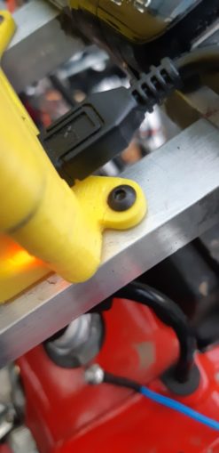
My shit welding failed, predictably.
Bit of JB weld epoxy on that and it’ll be good again. No way to easily remove it to re-braze to be honest. Unfortunately in the field test Dad insisted on, the gearbox seized up. A little play in it but the mechanism was utterly jammed.
This meant I have to take the gearbox apart. Again.
Two hours of the spanners and the main axle is removed.
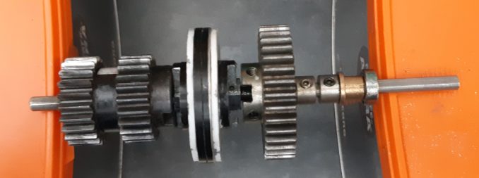
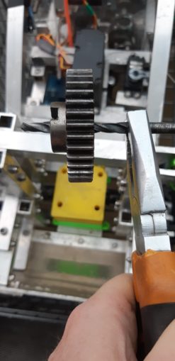
Rolling it across the tops of the big coffee boxes shows there is a definite preference for one side of the gears to be pointing down. Aside from one of the gears not turning, this can only mean that the shaft is bent.
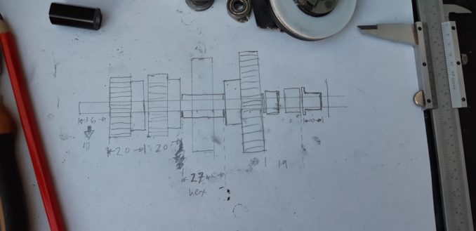
First off, I measure everything. All of the pieces that bind to the shaft have been placed carefully and I don’t want to have to repeat that process in situ again when I rebuild the shaft.
The gear that no longer rotates freely is a little tricky to pull off but it does come off eventually.
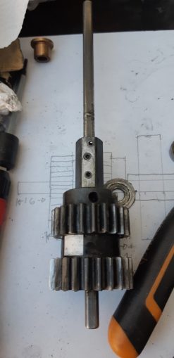
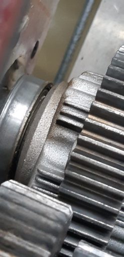
And now we can see what the problem is.
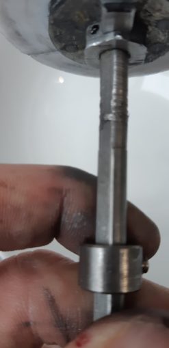
Somehow, heat and friction have produced a lump in the shaft. I genuinely have no idea how this could be – is it the swarf from where the shaft has worn getting collected by the empty grub screw hole, heating up and being deposited on the shaft?
Answers in the comments which I will not read.
This is the second problem – not only does the shaft have a burr on it which is stopping the freewheel, it is most definitely bent.
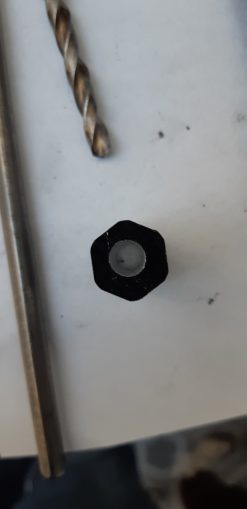
Repairs begin with the gear wheel itself, on a new shaft it will not spin freely. So I hang it on a 6mm drill bit and just spin it over and over until whatever is inside it is smoothed down.
I try to make another hex slider for the gear changer to move along but my drilling is well out of whack. The interior is 5mm and I need 6.
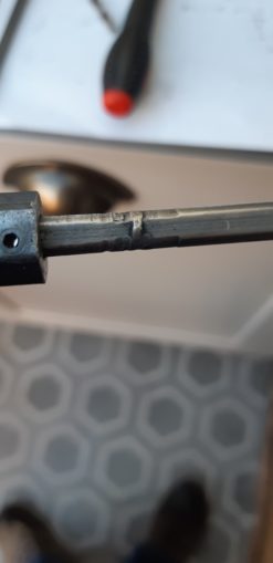
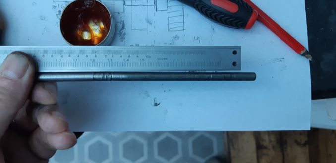
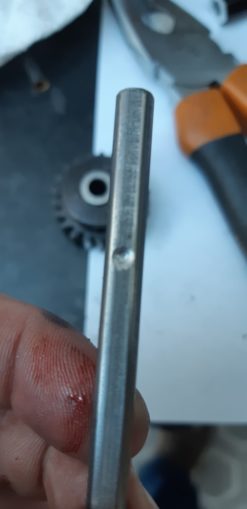
Based on experience, the grub screw has a hard time binding to the flat of the drive shaft. Now that I have my drawing of measurements, I can cut a little dent in the shaft to accept the tip of the grubscrew and hopefully get a better grip between the gear and the shaft.
It would appear the wind blew the cover off my workmate in the luxury custom built machine shop and the rain got in to the vice.
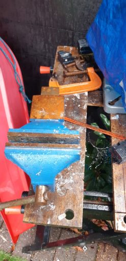
I am not best happy about this but at the end of the day the vice was dirt cheap and I hope I can restore it when I get a proper shed.
As I put the gearbox back together I notice signs of further wear and tear. At the minute it is mostly cosmetic and is shiny rather than indented, the photo looks worse than it actually is. It passes the finger test, anyway, smooth and level.
In amongst all of this woe as the Cnutmobile falls apart and needs rebuilding, at least my day was not as bad as this.
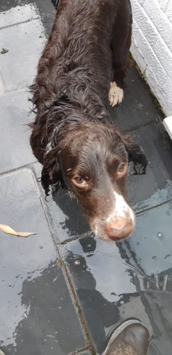
El Woofador could not resist rolling in a dead baby pigeon he found in the field one morning and subsequently had to be thoroughly scrubbed before he’d be let anywhere near indoors.
Now all that is left is to rework the RPM counters. I think they are getting jiggled about way too much, and the focussing / aim of the beams needs sorting out. Using a cut up USB adapter cable, I can power the laser on my kitchen worktop. After measuring the distance between the end of the sensor and the reflective panel on the gear wheel, I recreate it on the worktop so I can adjust the angle of the sensor and the laser so that at the focal length that will be used, the laser is reflected back on to the sensor itself. Once that is right, I can glue everything in place with Araldite epoxy
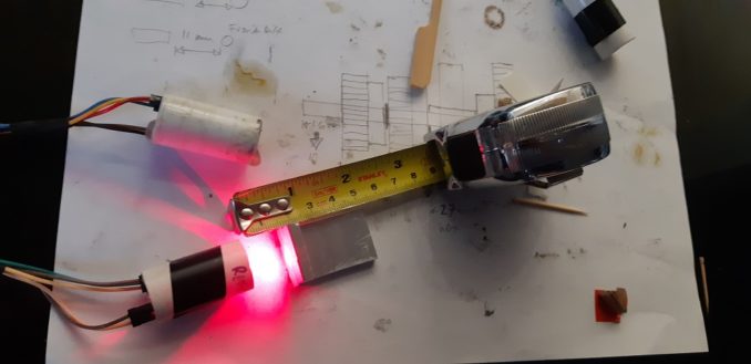
If you look really hard you can see the reflective strip on the aluminium L piece. What I really need to do is put the Araldite on in place, and have the laser on at the same time. I know that cured Araldite does not conduct electricity but I am unsure of the conductivity of wet epoxy.
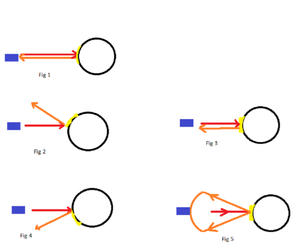
One thing did occur to me – as the laser is pointing at (hopefully) the centre of the axle, the reflector beams it straight back with a little diffusion which makes it larger than the thin laser beam going out. I still have to be quite accurate with the aim though, as per Fig 1 in the above. The blue block is the sensor, the red line is the laser out, the orange line is the reflection and the black circle is the gear boss.
Now, if I was to make the reflector flat rather than curved, I would get an angle of refraction which is what Figs 2-4 show – as the flat reflector moves in a circle, the reflected laser will strafe the sensor as per Fig 5 which _should_ give me a little leeway on getting the sensors aimed accurately.
For now, the Cnutmobile is fully rebuilt, sensors hopefully targeted properly, all I need is a couple of days free of rain and an hour free at the weekend. House move is “imminent” though so we shall see…
This was written over a week ago and Pater Cnut is fully on the mend, if any concerned puffins were fretting.
Still waiting for:
Nothing!
Still left to do / think about
End point adjustment for servos and control mechanisms Dumbo RC setup
Sort out some actual working brakes
Body shell
Affix fuel tank so it does not bounce about
Move gearchanger to 3 position switch on Tx
Move electric motor off throttle channel
Look at how Root superchargers work
Pics, vids, words and music © El Cnutador 2021


