
Welcome back to Cnuteneering, where the possible is made more difficult by bone headed ignorance, overenthusiasm and pointy metal things being brought together.
You may want to refresh your memory on the project in:
Design goals:
Fast as possible on offroad; too big to have on roads. I will set a target speed of 50mph.
4 WD.
Must be able to reverse, and brake.
Unbreakable, or as close to.
Must be able to mount GoPro or similar camera on it.
Cheap as possible.
We left the last episode of Cnuteneering with a field test under our belts, showcasing RPM counter failure and a bit of a lack in the 50mph direction. The gear changer is still causing problems and the speed is definitely a fail.
What is really needed is some proper field test data so the gear changer is all fixed up and we are ready to go.
In the video above you can see the top speed is way off, there is only one RPM counter working and it still looks like I am testing on Mars.
However, the TelePi is now logging all data to a file as well as the video capture overlay so I can at least do some post mortem. The only info that is missing is which gear I am in, so I am mostly relying on memory for “at what point did I hit 2nd gear”? A hand waving in front of the camera is usually my signal that a 2nd gear test is included in the next minute or 2 of footage. I can save about 30 mins total of footage without being in any danger of running out of disk space on the Pi, which is longer than I’d want to run the car for without letting it cool down a bit first.

Only getting reliable stats from the front diff RPM counter so that is bad, but at least I have something to go on. Max RPM of 6300 is pretty good.
Enough enjoying driving the car, back to base and let’s get the Cnutmobile faffed with to get the other RPM sensors fixed up, and then I can see what is going on a bit better.
I need to work on my video editing skillz so I can blur the video GPS reading otherwise I upload the GPS location of my back garden, which would be bad. Any recommendations for freeware video editing stuff that can do blurring / blanking out of selected parts of the screen?

I have now fixed the rear diff RPM counter but the engine RPM counter just does not want to play – the range may be too long in daylight from the sensor to the reflective pad. I am getting a max 6660 RPM though which is most gratifying. At this point I realise I have not really looked at how the logging code is working once I grafted it from the test harness standalone program and put it in to the main capture everything program. There are some unnecessary delays in the code, and our very own leopard suggested that the sample size be variable depending on RPM.

These code snippets (separated by the blue line) show how the wait and then the RPM multiplier are defined above the line. They are then used in the code to determine how often we should be sampling. As the RPM increases, the time between measurement intervals decreases. Hopefully this adaptive approach will give me some more accuracy / timeliness on the counts.
All of this testing has taken a toll on the gear changer though, predictably. I just can’t get the gear change right, although I did manage a few in motion gearchanges when I was field testing, which I am pretty chuffed about.
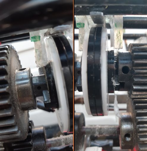
In the left hand picture above, you can see the 1st gear side of the changer getting slaughtered, and the 2nd gear beginning to show signs of wear. I clearly need to fix this before I run the car again.
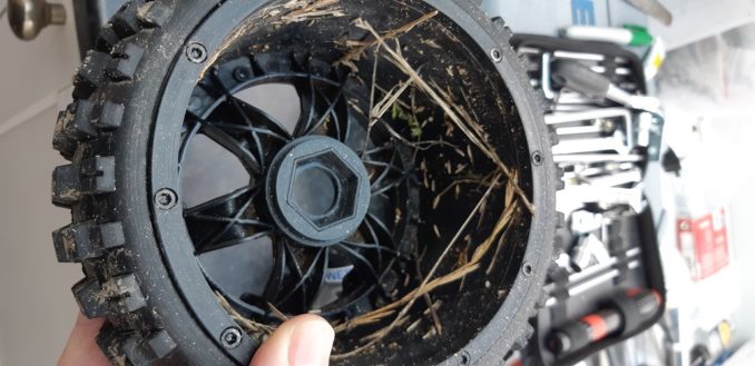
It is clear though with winter approaching and the places I have available to test being mostly marshland, I am going to have to protect the car from rain, bits of grass and puddles.
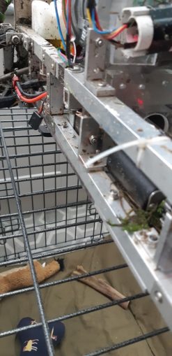
The grass gets bloody everywhere!
A bit of redesign, a few quid on ebay and the mark 5( is it 5? I have lost count) Gearchanger is build and ready to go. I am not sure how many iterations remain, but as ever I sit in hope – this time it’ll work, surely this time. A bit like communism, really.

Installation goes smoothly
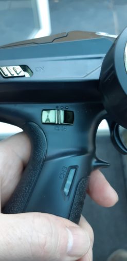
I do need to get a bit better at gear changing though so I mark how far the knob on the top of the Tx has to be turned to keep the interlock meshed in 1st and 3nd gear. Longer term I should adjust the Tx endpoints I suppose.
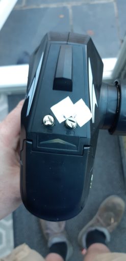
Or perhaps I could shift channel and use this instead – a nice digital “in first gear, in second gear, in neutral” kind of thing. This will mean disassembling the Rx housing and faffing about quite a bit I would think. Plus definitely doing som Tx Endpoint adjustments.
I really do need to put some mechanical brakes on the thing though and I rough out an idea or two.
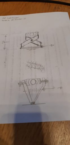
In the above, top drawing is basically a copy of bike brakes but turned upside down; the brake cable (direction of pull shown with an arrow) pulls the bottom of the scissors which pulls the top part of the levers into the rear driveshaft. I reckon I could use bike brake blocks as my brake pads, with a spring (200) along the brake cable line between the brake levers to push them open when not in use.
A simpler idea is a V shape, again with a spring along the brake line but I get no mechanical advantage on this and I have no idea how hard I need to grip the shaft. So to speak.
Accordingly I contact my custom state of the art 3d modelling department and they put together a simple prototype of the bike brake design. I only have 36 mm to work with, from the bottom of the cars skidplate to the top of the driveshaft, which is not a lot of space to muck about with.
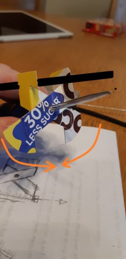
The thick black line is the driveshaft, and the orange arrows show how the cantilevers are pulled together. Unfortunately even at this size it will not really fit inside the space I have available, which means it is back to the drawing board. Again.
For now though, I have updated the TelePi software, and try to fix the engine RPM sensor. With all of the pulling about and whatnot, disaster strikes! Again.

As you can see, the mounting lug has fallen off the circuitboard. Should be able to solder it back on, I hope. That is for another day, the sun is shining and it is time to take the Cnutmobile out and race it to burnout gather some more valuable running data.
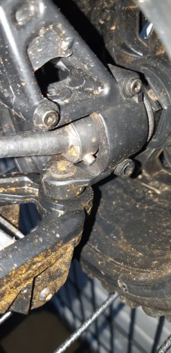
On startup, the car is sluggish and it seems that all the power is being pushed through the front right wheel. The car is clearly going nowhere so I pack it back into the car in despair and put it back into my garage. The problem is immediately obvious:

The cotter pin in the CV joint has just fallen out (red circle) and worse, as it was falling out it has eaten away part of the steering knuckle (tallow circle). A look at the other side of the car shows exactly the same, but at least I still have the pin.
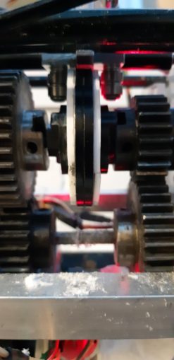
This is what a working CV joint looks like:

And now I see how it is affixed:
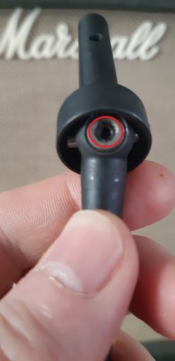
Two grub screws either side hold it in place. Obviously they were not threadlocked in place and that is why they have shaken loose. I will also put a band around the outside I think, just to be sure they don’t fall off again.
At the minute I am seeing quite a lot of disassembly – both front CV joints, the Rx unit rejigging. I may as well go the whole hog and check to see if the speed tailoff I am encountering at 90-100% throttle is due to the electric motor. Having proved that the braking it provides is vestigial at best, what I can do is move it to another channel so it is not involved in the throttle trigger at all.
This means I still get reverse, don’t have to rework the electrics too badly to get my 11.1v battery (ESC provides BEC function to bring the voltage down to 5v) and don’t have the problem of wanting 0-80% of the throttle in reverse to be mechanical brake and 80-100% of travel to engage reverse.
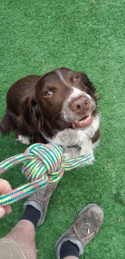
Quite a bit of thinking and tinkering to be done now I reckon, plus some research on supercharger design and build to try to squeeze a bit more juice from the engine, but in the meantime there is always other diversions…
Still waiting for:
Nothing!
Still left to do / think about
End point adjustment for servos and control mechanisms Dumbo RC setup
Sort out some actual working brakes
Body shell
Affix fuel tank so it does not bounce about
Move gearchanger to 3 position switch on Tx
Move electric motor off throttle channel
Look at how Root superchargers work
Pics, vids, words and music © El Cnutador 2021


