
Welcome back to Cnuteneering, where the possible is made more difficult by bone headed ignorance, overenthusiasm and pointy metal things being brought together.
You may want to refresh your memory on the project in:
Design goals:
Fast as possible on offroad; too big to have on roads. I will set a target speed of 50mph.
4 WD.
Must be able to reverse, and brake.
Unbreakable, or as close to.
Must be able to mount GoPro or similar camera on it.
Cheap as possible.
We left the last episode of Cnuteneering at getting the back end mostly sorted except the differential gearbox, and the engine and gearbox are now firmly attached to the chassis. This is a double episode to catch up with where I am at so I can avail myself of the wisdom of the puffinati without having to explain too much. Thanks to Jerry Mandarin for the tip on tougher bolts, and to leopard and Old Trout plus others for some maths stuff where I could not see the obvious and was making it difficult for myself for no good reason.
Next, I can finally sort out a bane of moving the gearbox about, the central differential which has been hanging off the bottom of the gearbox for months. The protective Lammy Washer between two of the gears – which I hope protects the opposing gears from hitting each other in the event of a gearbox implosion just about holds the diff in place but needs supporting on the other end as well.
This support needs to be mounted to the chassis itself. It is by design it is this low, but it has been a right pain supporting it when moving the gearbox and protecting the worktop / dining table from it when putting it down.
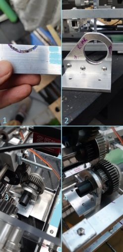
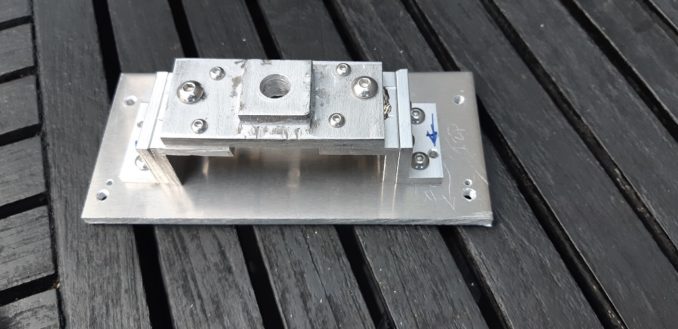
In the picture above, I first need to take a little semi circle out of the angle aluminium L shaped bar so that it is not in the way of the bearing. I do this by drilling a series of small holes in it. In pic 2 I have shaped the big upright with the bearing mount hole in so as to allow clearance for the other gears, and fastened the L bracket to it by drilling and tapping the aluminium plate.
In pics 3 and 4, you can see the bottom plate that mounts to the chassis itself, and the support bolted in place. I have left the overhang of the L plate for now, as it may come in handy later. Then again, it may get in the way again later but it is only 4 bolts to remove and I can cut it off.
I need to turn my attention to the front of the car now – the gearbox is firmly in its forever place now so I can work out how the front of the car is going to work. Previously this issue has sat on the THTTARN pile, simply because there is a _lot_ going on in this part of the car, and it all moves or rotates.
Using my fully equipped research laboratory garage, I have to lift the chassis above the table on a custom hi-tech lifting rig made by Heinz just to get the bottom suspension arms level with the bottom of the chassis. There are stubs protruding down on the ends of the suspension arms, which knacker any attempts at getting things level if I just put it directly on a flat surface.

This means I can check the travel of the steering turnbuckle as it moves side to side with the servo, and up and down with the suspension.
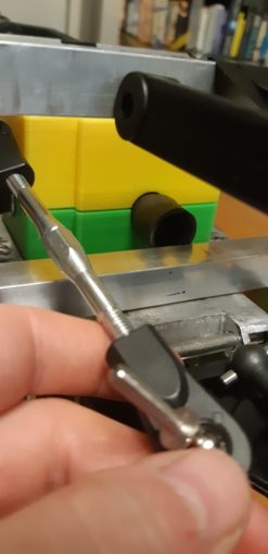
Undoubtedly this is going to be a problem, not least because the turnbuckles are for a much narrower car. I think I can see a way through it but it is going to need some careful thought on how the steering yoke is arranged.
At the moment the whole steering assembly is taking quite a bit of longtitudal space. The driveshaft passes under the support so it needs to be higher than I’d like, from the bottom of the car. I temporarily attached a spare bit of polycarbonate to the steering yoke to get an idea of the level in relation to the upper and lower rectangles of the chassis, and then realise this might be the solution to my short turnbuckle problem.
It will almost certainly alter the geometry of the steering Ackerman action so I will definitely have to suck it and see when I get the other components in the front of the car into their forever spots.
It also means the car is longer than it really needs to be. One design feature that is common on all my existing RC cars is that there is next to no empty space in the cockpit – everywhere has something in it.
In a flash of true thinking outside the box inspiration, I come up with this:
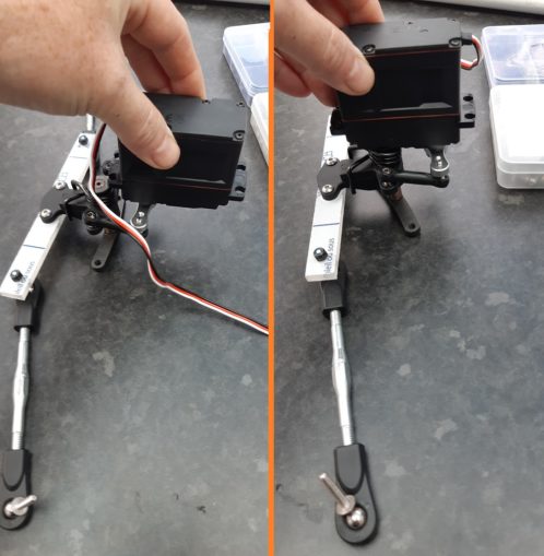
In the left hand picture is how the arrangement works in a normal HPI Baja car. Detaching the servo from the steering yoke and reattaching it facing the other direction saves me about 45 mm lengthwise which is a total result. Both the servo and the yoke are going to have to be fastened to the chassis Very Firmly Indeed. Having the polycarbonate involved in the steering chain might be a good fixture as a sacrificial breaking point – 15x20x5 mm polycarbonate is cheap as chips, powerful servos are not.
This also means that the front differential is close enough to the central diff so I can use one of the dogbones that came with the CV joints for the car to drive it. I am very, very pleased with this as up until now I thought I would have to make one.
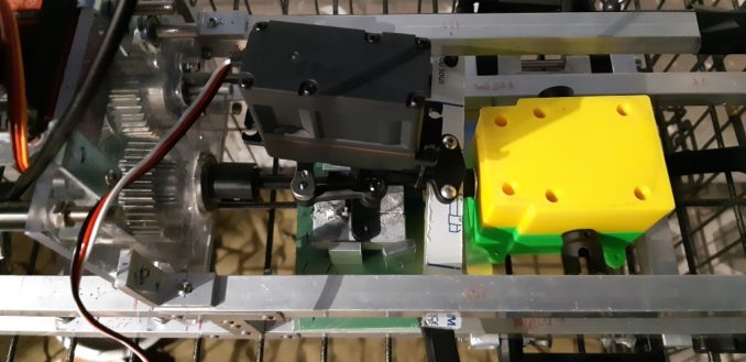
Using a handy bit of wood from The Shed Of Powah I can see how the fixing needs to be. I will need a solid plate with a couple of risers either side of the driveshaft for the little holes in the top of the black thing. Technical jargon, eh!
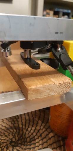
I may have to trim some of the differential gearbox away though in the yellow top part. Luckily I have a 3d model I can do that in and make sure that the unit is still going to stay together correctly, eh? The little lugs on the side of the gearboxes though are just too weedy I think.
What would be best would be to have a supporting plate underneath them and have some holes drilled and tapped into the bottom of the gearbox to accept bolts from below. The gearboxes don’t really need holding down so much as stopping them sliding forward if when I crash into stuff.
With some puffins showing off their new workshop gear and (rightly) criticising my piss poor brazing efforts, a reminder of my fancy fully equipped workshop:

Front Workmate to back – bench grinder, angle grinder in jig, 5” vice, cheap shit drill press.
With this fully featured and equipped workshop, I am able to build the Cnutmobile.
The front top suspension arm is going to need a lot of faffing as the attachment to the body is so odd. I line up some angle iron, true the cutting jig and get chopping some 15mm sections to use as holders for the bolts that will attach it to the chassis. There are quite a lot of them and the day was quite hot and I got a reminder of why we keep the guards on machinery in place and wear protective gear.
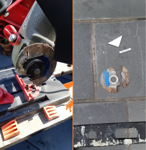
The grinding disc shattered under very low pressure and was caught by the safety guard so it did not harm me in any way.
I need 8 angled pieces to attach the arm to the chassis so it is time for some mass production.

I have solved the drill skitter problem by firstly putting a really deep centre punch into the metal. Then drilling a 2mm hole, slowly until the drill bit has established a hole. Then a bit change to a 3.5mm bit, then a 5mm and finally up to a 6. Lastly, a very quick blast with a 9mm drill bit to de-burr the hole edges.
This is a time consuming way to do it but it does seem to give more accurate results. The parts are now ready to go on the car, once the mounting bolts have arrived.
In the meantime there is more brazing to do. In order to provide a platform to mount the gearboxes on, I need to braze a 4mm plate across the suspension supports. Being the lazy cnut I am, I don’t want to have to take the whole suspension assembly together but the arms are plastic so I have to be careful with them and heat from the brazing torch.
So I get some old teatowels, soak them in water and lay them across the aluminium in order to leach the heat away from the ends of the assembly, with bricks on to keep them from moving around. You can see the teatowel on the bottom right of the next pic. I know I am playing with fire (hah) here so I give up before the aluminium is hot and ready to braze as I can smell a little burning plastic.
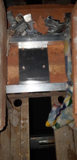
No real harm done though, a little surface abrasion but less than a mm deep. Phew!
I have to wait for the parts to cool down before I can start moving them about again, disconnect everything bar the 3 bits of metal and then I am away.
The key to success appears to be getting the bricks up to temperature first, and the torch seems to take a while too. In any case, I have a strong weld and a platform to mount the diff gearbox on, just add M4 bolts and I am away. I think what was going wrong before is that the aluminium was just cooling too quickly, so the window of hot enough to melt the solder and melting the actual piece was quite narrow. With the bricks in place, the window is much wider and I can braze with a lot more confidence.
I have to repeat this again on the rear of the car which is when the Hostage To Fortune Nut becomes a problem. Not insurmountable, just a lot more bolts to undo than I’d like. And then getting the upright out was something of a challenge, so I cut a channel in one side so I can just slide the piece out. But, more faffing about than I would have liked.
The rear is now built for everything’s forever place so I am pretty happy about that.
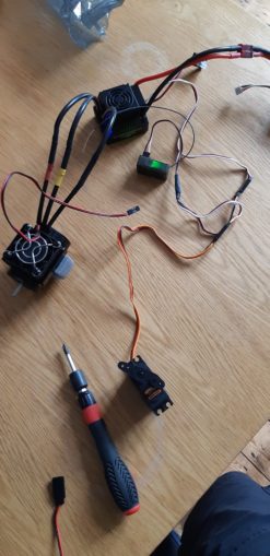
I now need to turn my attention to the electric motor that is going to act as my brakes and reverse gear. For once I have had a supply chain success, and bought it before I needed it and it arrived a week ago.
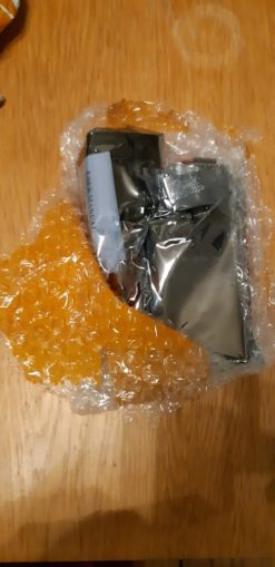
Much like my workshop, no expense spared on this packaging! I have a motor, an ESC (speed controller that drives a 3 cable brushless motor) and also provides a nice low 5v power supply via a clever bit of circuitry called a BEC to the Rx and possibly the rest of the car, plus a programming card for the ESC) and a fan that clips to the motor. The BEC turns the 11.1v from the battery into something the Rx and potentially other electrical bits can use.
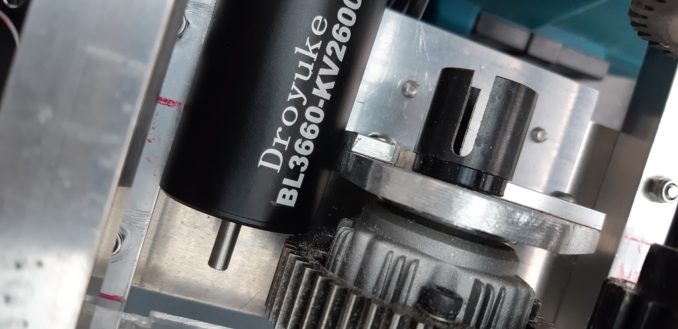
So now I just need to work out how to fit it. I even have a 1.25Mod gear that will fit the central diff and the motor axle if I can get my Braheelian mate to drill and tap a hole for the grubscrew.
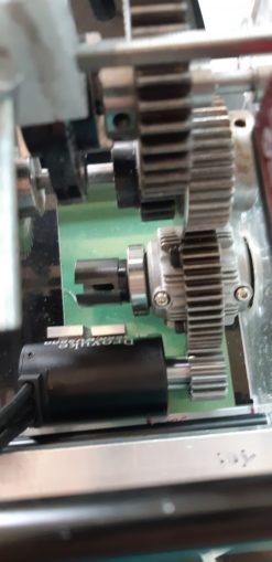
The upright that supports the central diff is not in this picture but I have cut it so I think it will not be in the way. I need to work out how exactly I am going to attach the motor to the chassis though; there are holes on the front of the engine but there is not an awful lot of space to get a driver in there to tighten them up.
Also the black rod running left to right across the bottom of the gearbox plates is totally in the way so it might need to come out for now. I can see if I can do without it, move it higher up or if I can fit it back in once the engine is bolted on.
Before I do that though I need to get the drive train in, and the steering all sorted out.
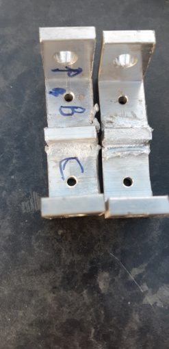
We started the process with a little light drilling and tapping. The holes had to be drilled to quite exacting depths or they will mean that the drill bit comes up against the diff central gear, so a bit of insulating tape on the drill bit to mark depth and we are away.
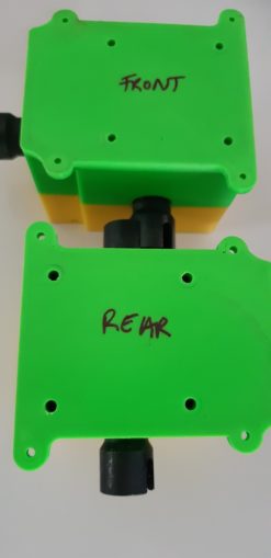
These are all custom holes so I have to be careful not to mix up the front and back units. One thing I have learned is mark everything as intermittent Cnuteneering can lead to mistakes unless each part is clearly labelled as to where it should go. Not that I have ever made that mistake /looks at shoes, whistles nonchalantly.
Next up is the steering plate. I need to support the steering yoke which has a funny slightly curved bar above a round bar. I can see no useful pictures of how this mounts to a proper car, only stock single action side mounted steering mechanisms. So as ever, it’s a take a look at it and see what we can do…
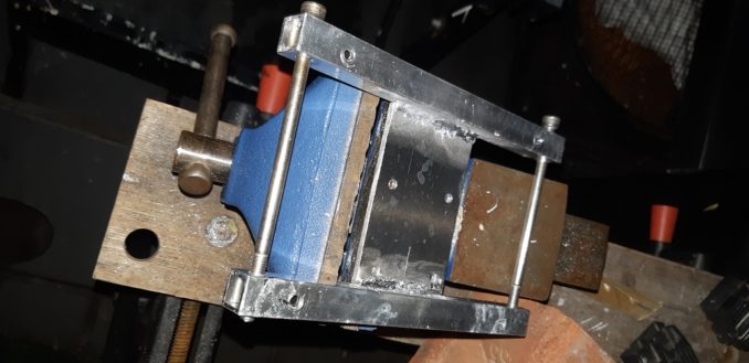
First I need to make something to hold the yoke, and be thick enough to support the round bar fully.
I cut some aluminium plate, 6mm and 4mm to make up the full 10mm length of the mounting bar, and bolt them together with a central hole. I can then braze them together so that there are no nuts and bolt heads sticking up. This bit is going to mount close to moving parts so I want it getting in the way of as little as possible.
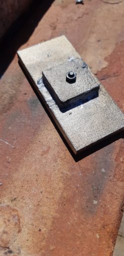
The Steering plate needs to mount firmly to the chassis, so a bit more fettling is needed to lift it above the drive shaft that will pass underneath it. I am careful to tap the holes to fix the bolts in as there is little space for the nuts to protrude.
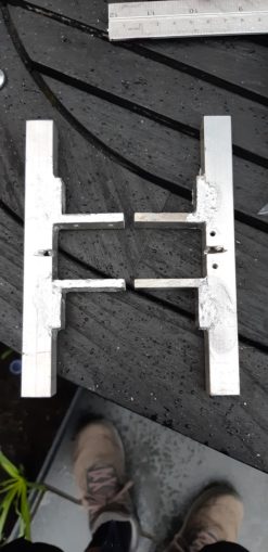
Eventually I am done, and the plate is completed.
This is now ready to mount on to the chassis, in the pic above you can see the mounting holes by the left and right sides.
Eagle eyed readers will have spotted the additional pilot holes that were drilled in the plate that mounts to the chassis. By no means was this a mistake caused by failure to label correctly in between Cnuteneering sessions, oh no, it was a deliberate method to uhmmm… Reduce weight.
Yep that’s it, to reduce weight, honest. Not caused by scrambling to put everything away prior to strangers visiting my house to see if they would like to buy it, at short notice.
And finally, we have the steering almost mounted completely.

I just need to machine some cross pieces to support the servo and the steering yoke is done. I will need to work out how to put the connection from the servo to the knuckle horns on the wheels but I think that will be just a few bits of polycarbonate and maybe aluminium. We have a new pile to go next to the THTTARN pile, the Sort It Out Later pile. This is stuff that isn’t really a problem but does need doing.
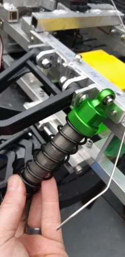
The last bit of big Cnuteneering that needs to be done on the car is to get the front shock tower built. Before I can do this I need to solve the front suspension conundrum.
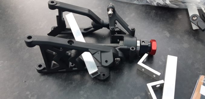
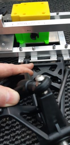
In the picture below you can see the bottom front suspension arm.

The bottom arm is attached to the chassis, the top arm is flapping around uselessly as I have not attached it yet. On a 2WD car like this the shock absorber goes through the middle and mounts to a pin that goes through a hole in the red circles – the little circle is the mount point at the back of the arm.
This poses a problem to me as you can see, the drive shaft also wants to go through my the same bit of space that the shock absorber should.
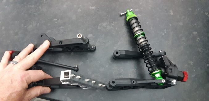
On the rear suspension arm, the shock is mounted after the drive shaft. So this is what I will need to do for the front of the car.
Before I can do that though I will need to attach the top suspension arm to the car, so I can see where the shock absorber can go. It could go either at the front or at the back of the suspension arm. All my “proper” cars have the shock absorbers at the front of the arms which is an expensive place to put them as the front of an RC car is usually the first to get smashed in a crash.
The reason they do this (aside from revenue in spares) is because the shock tower needs a firm mounting to the chassis, which is usually just a metal or carbon fibre tray at the bottom of the car. As I have metal above and below on the chassis, I think I get a bit more leeway on the placing of the tower.
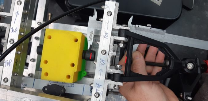
You can see it better in this pic:
The box section is where the shock absorber would go. I think if I brace between the lugs with some tubing section, and put a 5mm bolt through, that should do the job. Otherwise I will have to remove the lugs and sandwich the suspension arm between 2 plates of aluminium and get the fixing to the shock absorber that way.
But as ever, we shall have to suck it and see!
First, we need to get the top arms mounted to the chassis. This is a bit fiddlier than I would like; the arms are a bit wider than the rear so I need to mount above the top chassis rectangle.
Angle aluminium to the rescue again that I made earlier, Blue Peter style. The M4 bolts have arrived and I am ready to go. The legs on the angle aluminium are too long in the middle so they will need trimming back.
While cooking some rice for dinner, that gives me a 10 minute window for some guerrilla Cnuteneering, just enough time to lop off the ends of the angle ally and get it ready for braising.
Unfortunately, haste is never a good bedfellow for measuring, and I somehow managed to cut the ends too short. Before braising, I need a little fillip to put in, there is too much time invested in the cut ends so far to re-make them.
Duly done, sanded rough, acetone washed and gently G clamped in place with some bits of brick close by to retain heat.
These braises are much better. The trick is definitely supporting the braze with heat reflecting housebricks, I am thinking the 2mm box section just cools down too quickly.
The central supports just need affixing to the main body, then these components can go on the chassis.
This being Cnuteneering though, the centre mounts are square on the ends and stop the suspension arm from full travel. So out comes the hacksaw and the trusty Dremel (have I mentioned how much I love this bit of kit before?) and a short time later, we have the arms mounted to the chassis mounts.
I can now fit the suspension arms to the front of the car which is looking more car like every day now.
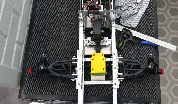
I can now move on to getting the steering servo held in place. Some sawing, drilling and then eventually braising and I get a mountable holder that can be bolted to the top rectangle of the chassis.
While rooting about in the Shed of Powah, I found an old crap G clamp that is perfect for holding stuff still. The trick is to not tighten it too hard to crush the warm aluminium but tight enough so nothing moves when it is being braised.
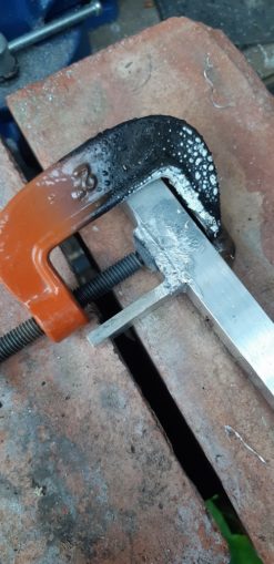
In any case, it makes all the difference. Back to the car and there is a nasty surprise in store – in my haste and joy at being able to use the spare dogbone driveshaft that came with the front / rear diff I focused on the wrong thing and ended up with this faux pas.
Yup, by moving the gearbox closer to the engine I spannered its location relative to the front sus arms, so the drive cups are totally out of line. FFS.
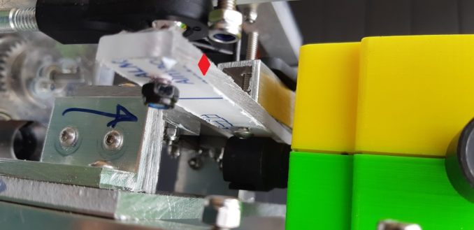
There was yet more joy as the Fuckup Fairy came to visit; trying to fix the crossbeam to the servo yoke I ran out of space; the red diamond is the polycarbonate crossbeam, attached to a bit of box section then to the steering yoke. You can see the polycarbonate strip resting neatly on the drive cup for the diff, so they will impede each other when moving.
/shakes fist.
On the plus side, once the steering servo mount had been put in, the location for the throttle servo became clear. As I have electric braking I don’t have to worry about the reverse stroke of the servo horn, so the throttle servo can be neatly mounted in line with the throttle cable.
Classic Cnuteneering, two mistakes and one success.
Now that all of the steering gubbins are settle in (except the crosspiece to turn the wheels, that needs some thought still), I can put the front shock tower in.
Some cutting and faffing and here we are:

This is something of a massive fail though as the shocks are just all wrong height wise:
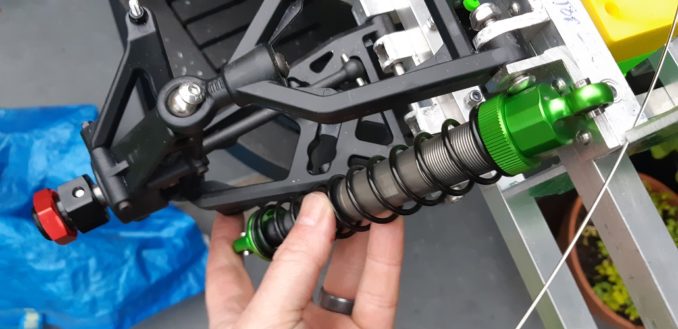
As you can see in this picture below the shock only just about comes to the top of the front suspension arm mount.
This is going to need some further thought. As will this – the dogbones in the CV joints to the wheels are too short by about 70mm – from red line to red line. I do potentially have a solution to this but I am not too sure that extending the shafts out to the edge of the chassis is going to be enough.
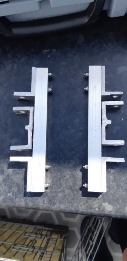
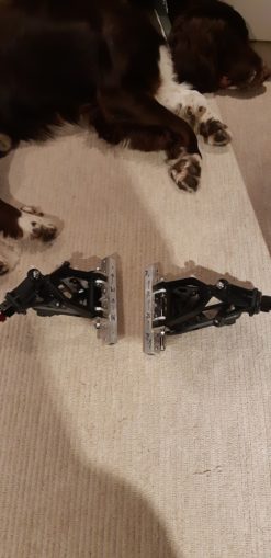
There is an unexpected difference in distance between the upper and lower suspension arms though, front suspension on left, rear on right:
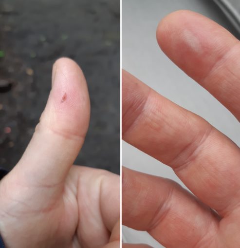
This is not the happy finish to the episode I was hoping for, not least for the injuries I have suffered.
At least I can retreat to my comfort zone of electrics for now though.
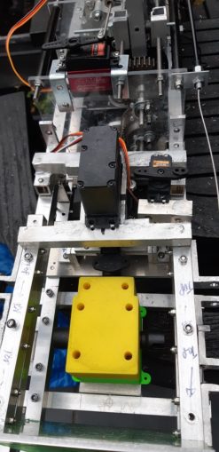
The motor is on the left, the ESC is at the top and the receiver has the happy green light on. The output from the throttle channel on the Rx is split into two – one goes to the ESC and the other to the throttle servo. It seems to work quite nicely, and on the ESC there is also a passthrough from the Rx so I can use that too if needed, just for 5v power if no signal is required too.
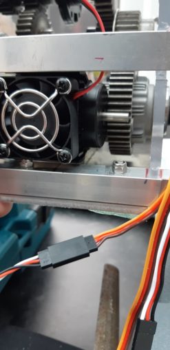
I think I can see a way to mount the engine once I remove the side support from the main gearbox.
And by lucky happenstance, the fan for the motor just about fits.
I shall leave it there for this episode on a mildly successful note. Lots of thinking to be done between now and next episode.
Still waiting for:
Bolts in various sizes, M3 and M4
Still left to do / think about
Design, build and fit the front shock tower
Sort out the car underside – at the minute it is just a gaping void with a few plates across it
End point adjustment for servos and control mechanisms Dumbo RC setup
Siting of RPM counters
Siting of battery and control gear
Bend the front of the chassis up or not?
Front and rear central driveshafts
Differential gearbox to wheel dogbone driveshafts
Attach electric brushless motor
Design and fit rollcage with picam mounting
Pics, vids, words and music © El Cnutador 2021
The Goodnight Vienna Audio file


