
* And outside.
Home automation seems all the rage in puffinland with various articles describing the setting up, care and feeding of home automations. We’ve had Automations in my home and
Smart Radiators, and I know many of you silent readers out there have had a go to try to save yourselves a few millions of pounds as our “government” imposes NetZero back to the caves living upon us all.
I have set up my home automations and aside from the occasional misconfiguration, it all works very nicely and it keeps getting better and better as time goes by. The emphasis on https://www.home-assistant.io/ seems to be voice control at the minute and that’s going to be a big game changer once they can get some easy to set up hardware to act as satellites to run the microphones. Obviously, voice control will need an input microphone in the room you are in and that needs to be able to talk to the main server running the automation software. At the minute it’s all a bit fiddly but it can be done so I will be keeping an eye on it this year.
What I really would like is some intelligence in the system to put the heating on or off depending on how cold it is outside. At the minute I can schedule each radiator (or groups of radiators) to come on or go off very easily, but given we’ve had some cold snaps and some warm spells, it’d be nice to have the heating come on in the morning dynamically. If it is colder at 5am than usual, the heating should come on a bit earlier; if it is warmer than expected then the heating should come on later.
In order to do that, I need to get an accurate, localised temperature reading from outside. I can get a whole load of outdoor temperature sensors but these are all battery powered and don’t seem to be set up for being left outside. There are full blown weather stations available but these are over a hundred quid I don’t need the wind speed and rainfall measuring. So I need a temperature sensor that doesn’t need a battery change every six months, and can be left outside.
And so a new discipline is born! Having given the world the concept of Cnuteneering, I now bring you Cnutelectronics! It comprises the same bone headed ignorance, overenthusiasm, poor research and very hot soldering irons.
Looking at the places I can put the device, the flat roof at the back of my house is ideal – the wifi signal should reach there and it is exposed enough to get a good temperature reading without getting any ambient heat from the house itself.
All good to go then, so off I trot to see what support for home made devices there is on HomeAssistant. Turns out there is a thriving homebrew community out there – https://esphome.io/ These solutions are centred around a cheap but very capable mini computer called an ESP32. Twin core, decent RAM, can connect to a computer over a USB and more critically – wifi on the chip. Ideal for my purposes.
I get on to t’internet and find several tutorials on how to put the hardware together, like this one https://www.circuitschools.com/interfacing-bmp280-with-esp-32-on-i2c-with-errors-and-solutions/ So I trot off to AliExpress and order some ESP32s – one to use and one to break, plus a few BMP280 sensors that measure air pressure (barometer) and temperature. I had no idea these sensors were so freely available. The ESP32s cost £3.25 each which is pretty low cost for what you get. I also get a mounting board as I don’t want to be soldering directly on chip pins.
The customary few weeks go by and I start to think about how I am going to power it all. I am thinking some rechargeable batteries and a solar panel or two.
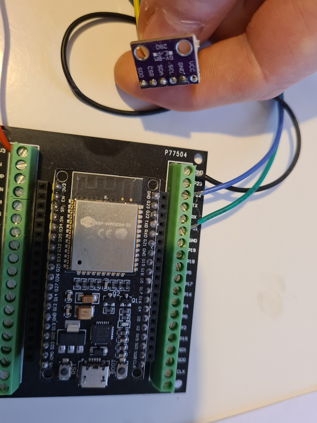
Following the guide I connect everything together. This chip is using the i2c protocol which is some kind of serial communications layer that sends the info in a stream of bits and bytes across a single wire, there is the so-called SCL pin which is a clock signal to keep the communications in sync, and the SDA wire which is the data itself, sent as a stream of 0’s and 1’s. The chip can support up to 115200 baud which isn’t much in these days of gigabit internet but at the end of the day all I am sending across the wire is temperature and pressure which is not a big amount of data by any means.
Here we have the first connections made:
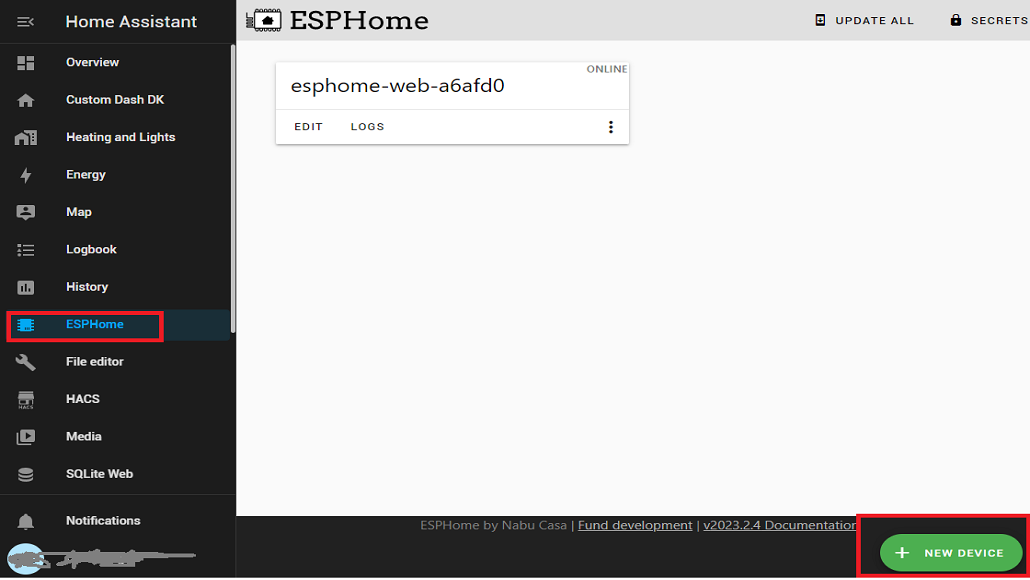
And then I need to install the ESPHome software on my Home Assistant server:
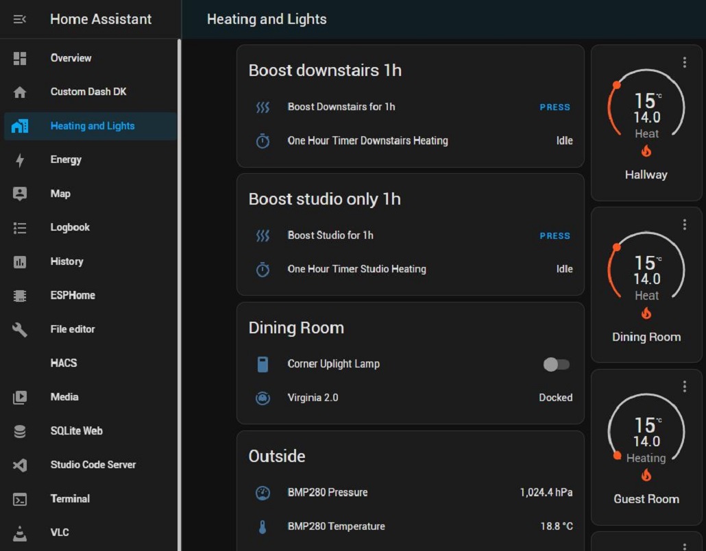
This is all pretty straightforward in the Home Assistant (HA) UI, and I get an extra sidebar entry showing that I have ESPHome running on the box.
I can now “Add device” as shown on the bottom of the picture here:
I feed in the WiFi credentials, and the ESP32 now has the HA code installed on it and is ready to go. I just need to configure it:
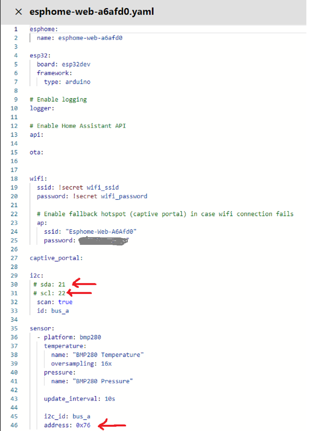
Here we have the 3 key pieces of info needed to tell the ESPHome how to run the device. I just tell it which pin the SDA, SCL wires are connected to, and the i2c address. I am using the default SDA/SCL wires so the values are commented out here.
The i2c address is to allow multiple devices to connect on the same SDA/SCL pair and for the software to know which device it is talking to. I only have the one device so this should not be a problem.
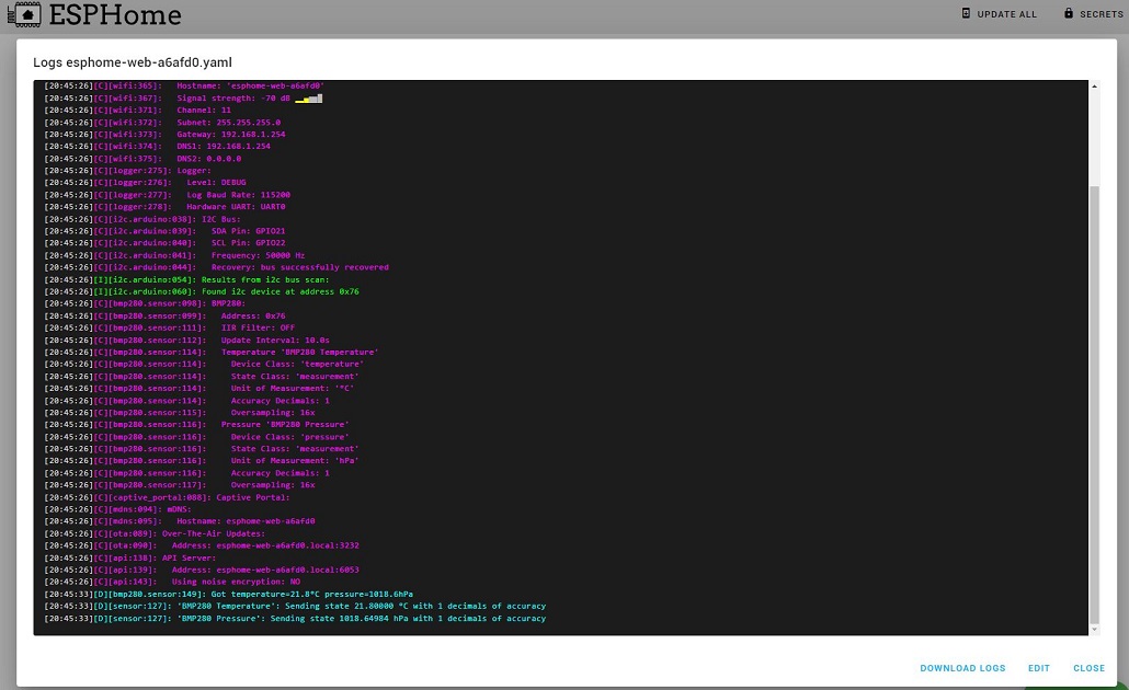
The install completes and the device is miraculously reading values back:
So now I need to work out how I am going to power the thing from a rechargeable battery. It is all powered from the 5v USB cable when I have it plugged in indoors but I am not running a socket up to the roof when it is put outside.
Some faffing about on the internet, and I get some valuable info. I can use a 4.2v rechargeable battery, get a magic chip that will sort out the charging of that battery, and then regulate that down to the 3.3v that the ESP32 wants feeding. There is in fact a whole load of magic chips out there called TP4056 that are specifically designed for this it seems, they will charge the battery and manage the output for me. How they work is a mystery but I read it on the internet so it must be true.
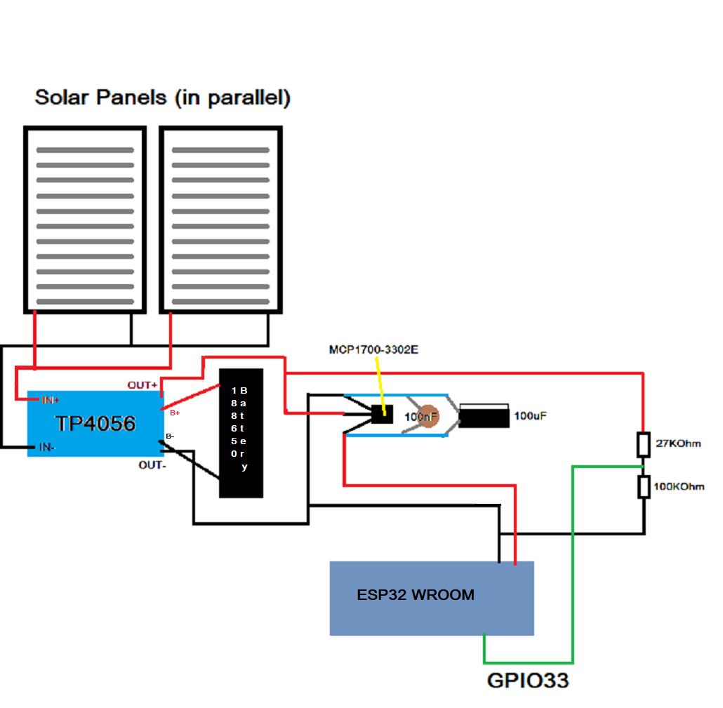
In the above, we have 2 solar panels feeding the magic chip that drives the battery, and then in turn the output is regulated by an MCP1700-3302E chip that keeps the voltage at a steady 3.3v as best it can. There’s also a couple of capacitors on the output which I think will smooth out any bumps in the voltage output. I have also added a voltage divider so I can hopefully see how much actual voltage is coming off the battery and see how it fares on recharging from our cold winter sun. The divider is needed because the battery will output up to 4.2v but the ESP32 can handle a maximum of 3.3v, so I need to scale it back a bit so I don’t fry the chip. The voltage divider just lets some of the voltage run off to ground, if you like.
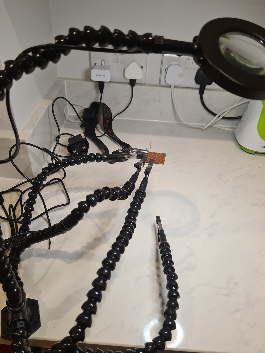
This is going to be quite a bit of soldering so I invest in a five hands and lit magnifying glass as shown below.
You can see the little bit of brown Veroboard I had left over from the control systems of the Cnutmobile with a couple of component legs poking though. Soldering is a job where you need 3 hands, have space for 2 and you have to be quick or the heat from the soldering iron will break the component by melting it. Veroboard is a hard heat resistant plastic that has a whole load of small holes in it, and on one side has copper tracks running parallel over the holes so you can link components together.
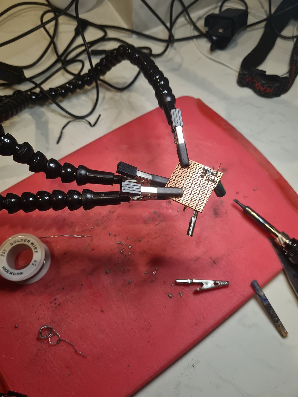
Progress is made and I am using a crocodile clip on each side of the brown Veroboard to hold the component in place while I solder. The crocodile clip on the underside is to absorb and dissipate any heat that comes through the component legs before it hits the component, and it also means the components are at a uniform height above the board. There must be #order! Soldering iron is set to ~325C and I aim to have it in contact with the components for no more than 3 seconds in one go to protect from melting everything. This is a bit of a new skill for me as usually I am just soldering wires together so can be a bit more generous with the heat.
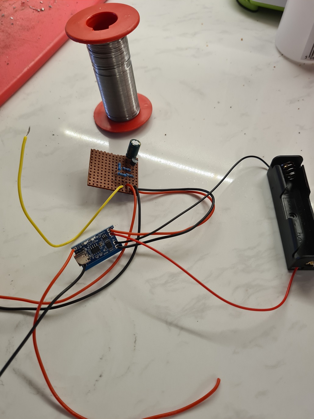
And here we have the completed master circuit. I did not have the right resistor values so I had to add a couple more in series to stack the resistance to the desired level.
Despite ordering the solar panels and the magic chips at the same time as the batteries, they are in Poland and have been for the last 3 weeks. Progress stalled for now.
I still need to:
Work out what I’m going to put the whole thing in that will keep it safe from the elements
Work out how to tell ESPHome that the input from the voltage divider needs to be presented.
/Shakes fist in Polish and Chinese.
Once the weather picks up and the house is a little more finished there will be a return to Cnuteneering. Oh yes there will be.
© El Cnutador 2023
The Goodnight Vienna Audio file


