
Welcome back to Cnuteneering, where the possible is made more difficult by bone headed ignorance, overenthusiasm and pointy metal things being brought together.
You may want to refresh your memory on the project in:
Part One.
Part Two.
Part Three.
Part Four.
Part Five.
Part Six.
Part Seven.
Part Eight.
Part Nine.
Part Ten.
Part Eleven.
Part Twelvety.
Part Thirteen.
Part Fourteen.
Part Fifteen.
Part Sixteen.
Part Seventeen.
Part Eighteen.
Part Nineteen.
(Yes I will tidy this bit up for Ep 21).
Design goals:
Fast as possible on offroad; too big to have on roads. I will set a target speed of 50mph.
4 WD.
Must be able to reverse, and brake.
Unbreakable, or as close to.
Must be able to mount GoPro or similar camera on it.
Cheap as possible.
We left the last episode of Cnuteneering at the rear end of proceedings, which for the most part went quite well. Some emergency internet shopping as I ran out of M3 bolts and of course, some waiting was required. There just has not been enough waiting so far.
I finally bit the bullet and integrated the RPM and temperature code into the video and GPS capture stuff and it seems to work. I even made a release build for it too so all the development cruft is flushed out of the compile and the app should run more efficiently. Aside from plugging in the new sensor when it arrives, the telemetry unit is officially DONE DONE.
I can now start bolting everything together; the idea is that the top rectangle of the car chassis can be unbolted from the bottom, and everything can be lifted out neatly for when I need to do maintenance.
So here we have the first of the steel plates bolted on from the bottom chassis rectangle to the upright.
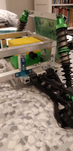
In the corners you can see the 90 degree plates holding things together. It gets bloody busy around the corner there but I have 2 bolts per side for strength. At the minute the bolts are just finger tightened, when I get everything ready for the final build then the ordinary nuts will be replaced with Nyloc anti undo nuts and threadlocked in place.
One problem I have is that the distance between the bottom and top chassis rectangles is 45 mm and the T plates (in blue, just above the bottom suspension arm in the pic above) are too long to fit one up and one down.
So I thought if I just put a little step bend, to raise the end of the piece up, I can put a single bolt through both T plates and the chassis. Easy eh?
Long suffering readers will know that is not the case in Cnuteneering. At first I clamped a T plate in my vice, and hammered it to 90 degrees. I then turned it over and put a cold chisel under the gap to hammer another, opposite direction bend in. This did not give me the gentle 1mm lift at the end of the T piece I was hoping for.
So I tried instead to clamp the piece in my vice and crush the bend into the plate.
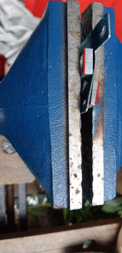
The red lines are where the little spacers are, to force the plate into the shape I want.
Needless to say I am still bereft of the neat 1mm step out that I wanted.
In this picture, the top plate is bent in the compression of the vice, the bottom is bent by hitting it with a big hammer. Not much difference, the step out is 3-4mm and I only need 1mm.
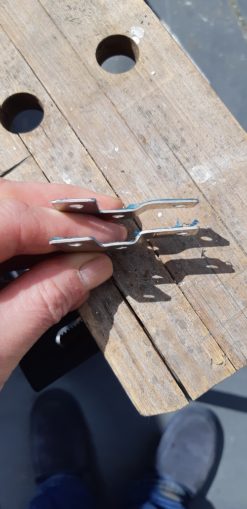
So I just sawed off the section with the second hole in it. I can now have two T plates facing each other, holding the upper and lower chassis in place. This also means I can mount the engine, gearbox and petrol tank.
Looking at the engine and gearbox from the side, the plate closest to the engine is flush with the bottom chassis; the plate furthest away is about 4-5mm above it. The engine itself is not completely level either which is bad. I am going to have to take a few mm off the bottom of the closest plate and get the engine nicely level.
This is not as easy as it sounds as the bottom of the engine is not flat, either. But this is Cnuteneering, where we do things by dead reckoning and smile through the tears of the rebuild when it all goes horribly wrong.
It will also be a pretty good test of how hard it will be to take the car apart – can I disengage the engine from the gearbox and remove it easily, and can I then get the gearbox out with a minimum of fuss? Before any holes are drilled this will be a useful exercise.
It also means the engine will be clear of the gearbox so I can fit and test the kill switch, which has been on my todo list for some time now.
Taking off the engine cover we can see the lead that goes to the existing manual killswitch.
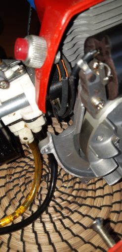
It basically shorts out the current from the magneto (like a little dynamo) that is used to fire the spark plug, to the engine casing “ground”.
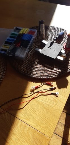
I just need a few leads and a handy pack of connectors from t’internet and I won’t need to do any soldering.
Oh wait, this is Cnuteneering and there are no shortcuts….
An early morning sunrise o’er the freshly crafted leads, gas soldering iron posed over the dead handy Bit Of Roof Slate.
Hours spent Cnuteneering are a little thin on the ground at the minute, what with having to do the house up so we can flog it, so just after Doggie Walks Matter I can sometimes sneak in a quick half hour of guerrilla Cnuteneering. The blessed period of time where everyone is asleep and as long as I am not running the angle grinder I can get a few bits done in peace.
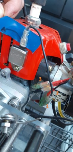
I have taken a feed from (1) the original connector block, and fed this to a splitter (2) which then retains the wiring to the original manual killswitch, and feeds the electronic kill switch in parallel (3). So now the engine will stop if I either press the kill button, or if the electronics decide it is time to die. If the transmitter signal is lost, if I click the kill switxh on the radio control transmitter or if the receiver is on low or no power, the engine will cut out. Safety first!
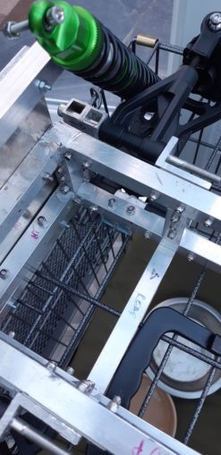
Now that I have disassembled the car for the first time it would appear that the gearbox has to slide all the way out the front. The cutaways on either side are just not big enough to rotate the gearbox and wiggle it out. I may have to revisit this in the future, but I am hoping that once it is in, it is in for good. I should be able to get at all the bits I need to without taking the gearbox off the car.
The M3/M4/ M5 nyloc nuts have arrived so I spend another couple of hours taking ordinary nuts off and replacing them with vibration proof forever nuts.
It gets bloody fiddly in the corners though, just as I anticipated. Lots of bolt heads and nuts going on.
Now that it is not freezing cold and pissing down in my fully appointed luxury workshop back patio, I actually have some success in braising the engine bracket together. Housebricks, a nice 30 degrees from vertical chamfer and some gentle pressure from a G clamp seem to work wonders; the solder pools in a pleasing puddle off the metal now and I get some decent looking joints with no burning metal deforming and sagging.

I use a couple of washers to level off the engine on its supports. This is pretty tricky though as there is no handy line running the edge of the engine block to tell me where the centre of the output shaft is.
The best I can do is hope that the engine casing is at 90 degrees to the shaft, and measure that vs the chassis rectangle.
We are not far off, the line you see between the orange arrows is less than half a millimetre (probably close to a third or a quarter) out according to the square I am using.
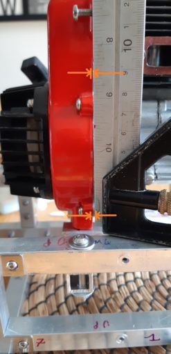
And this means that the gear shafts are looking nice and parallel to the chassis too. 6mm is still looking painfully weedy though.

All this faffing about with the engine height has now moved where I thought it actually would be, so I need to trim off around 4mm of the main gearbox plates so that the mounting holes line up with the engine again. My shiny new Dremel was the difference between a 10 minute job and a full on half day of gearbox disassembly.
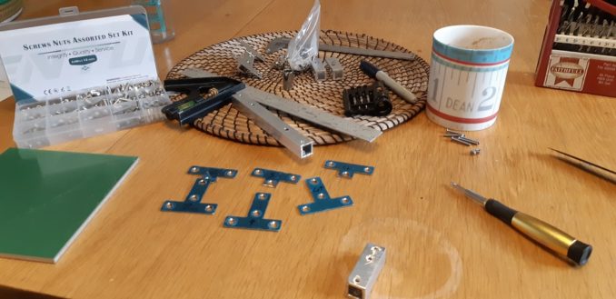
I pre-make the chassis linkages for the sides. These will support the top chassis rectangle on the bottom, and it is easier to make them with the bolts loose, then fit them to the car.
Now that I have the angle aluminium I can fit the rear top suspension to the top rectangle, and the rear of the car will be almost complete. I just need to fit the diff gearbox and drive shafts and I am away.
The angle grinder holder earned its place in the shed today; despite not cutting all the way through in one cut (blade diameter not big enough), I cut a lot of aluminium sections to 15mm for mounting things to the chasiss. I also cut a long length, about 50mm, to support the central diff bearing holder.
Having decided to use a brushless motor for braking and reverse, I will have to hang back on cutting this ready to be fitted as I need to see where the fixings for the motor will go. A brushless motor and ESC will give me the braking I need – ESCs are clever enough to see that the motor is still turning and will apply gentle reverse shocks to the direction of the motor until the motor is still. Further pushing the transmitter trigger in reverse will engage a continuous reverse pattern to the motor direction. A twofer, indeed.
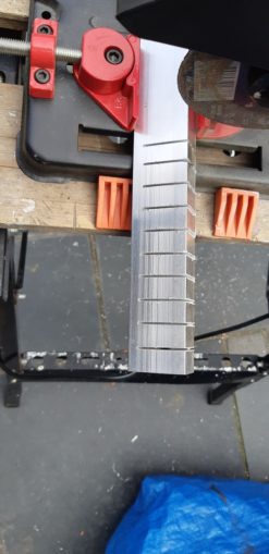
Many cuts made light work! Tools for the job make things so much quicker and easier.
I can also use these to mount the front top suspension and to hold the polycarbonate gearbox plates to the chassis.
Because the rear end of the car is so damn busy with bolts, I had to move things out and around a bit.
And here we have the top suspension mount for the rear of the car. I had to braze the L shaped bit at the back, put some holes in it and mount to the rear post. It is held away from the main chassis by a couple of thin bits of aluminium tube I had as offcuts from making the main gearbox spacers. A rule of Cnuteneering – keep all the offcuts as you never know what will come in handy. I hope this make it up as you go along design decision is not going to bite me any time soon…
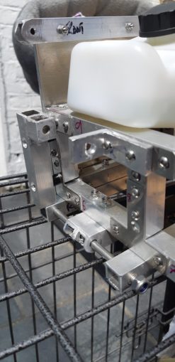
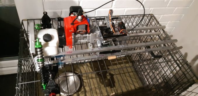
The main gearbox was not too dreadful to mount in place, a few bits of angle ally and away we go.

This now means I can go through and tighten all the bolts so far I think.
While doing so I sheared an M3 bolt, which is not a good development. My guesstimate of the strength may be way off, or it was just a bad bolt. I have used about 60 bolts of this size already though so I am a little worried that the whole car may fall apart because I did not use M4 bolts. We shall see.
As I wait for the electric engine (for brakes and reverse) to arrive, I am now nervously eying the THTTARN pile, knowing that the next step is to sort out the steering yoke and drive shafts. I can probably duck it for a little while as I get the front top suspension sorted out, but some hard thinking is going to be needed as I have to try and get the steering linkage so that it doesn’t get in the way of the driveshaft to the front diff, while making sure there is enough clearance for the arms to move up and down as the suspension flexes.
Hmmm.
Still waiting for:
Arriving 3 June 2021
Pack of 6, M6 x 85mm (6mm) A2 Stainless Socket Cap Screws with Free A2 Stainless Steel NYLOC Nuts (Pack of 6), Steel HEX Head
Pack of 20, M6 x 30mm Metric A2 Stainless Steel DIN 7380 Socket Button Head Screw Bolts, Plus 20 x NYLOC Nuts, 20 x Spring WASHERS & 20 x Flat WASHERS
Arriving 4-7 June
Draper 33591 2.0mm Metric Hexagon and Ball End Hexagon Key
A2 Stainless Steel Button Dome Head Bolt Screw M4-40mm – 10 Pack
Brushless motor etc – Arriving Jun 15
Pinion gear for motor – Arriving Jun 3rd
Still left to do / think about
Sort out the car underside – at the minute it is just a gaping void
End point adjustment for servos and control mechanisms Dumbo RC setup
Build last RPM counter, got the parts ready to go now.
Siting of RPM counters
Front end siting of servo and steering yoke
Siting of battery and control gear
Bend the front of the chassis up or not?
Pics, vids, words and music © El Cnutador 2021
The Goodnight Vienna Audio file


