Welcome back to Cnuteneering, where the possible is made more difficult by bone headed ignorance, overenthusiasm and pointy metal things being brought together.
You may want to refresh your memory on the project in:
Part One.
Part Two.
Part Three.
Part Four.
Part Five.
Part Six.
Part Seven.
Part Eight.
Part Nine.
Part Ten.
Part Eleven.
Part Twelvety.
Design goals:
Fast as possible on offroad; too big to have on roads. I will set a target speed of 50mph.
4 WD.
Must be able to reverse, and brake.
Unbreakable, or as close to.
Must be able to mount GoPro or similar camera on it.
Cheap as possible.
We left the last episode of Cnuteneering at some successful brazing, some successful tech stuff to capture video, measure and capture speed and an eye on other things to measure what with me being a near autistic systemiser and all that.
Arrived: a DS18B20 temperature sensor to attach to the engine, some LED emitters and receivers to make 2 RPM counters out of.
Just a few little bits to pick up along the way, as ever. It was a Friday when I was looking for a stainless steel brush to clean the aluminium box section with but this came up:

I tried the safety cutout switch on my plane Rx and it just plane (/coat) does not work. Bugger. /Shakes fist in Chy-Nese, throws prawn crackers.
Instead, I bought a safety cutout switch from these folks and was delighted at the speed of service, their almost immediate tech support and a product that actually works. If the Tx is out of range, then the Rx goes into failsafe and puts the throttle to neutral. If power is lost or flaky to Rx, the engine is cut. If the signal from Rx to the cutout is in any way weak or not right, the engine gets cut. If I choose to kill the engine, I just click a button on the Tx and it cuts out. That is about as safe as I can get things I think.
At the time of writing I was supposed to have spent the last weekend brazing up the chassis frame but was duped encouraged to do some gardening instead. On the plus side, I did get to use my Chy-nese tool to cut the steel fencepost I was installing and it passed with flying colours. And I got to buy a big jug of acetone which is great for cleaning mucky fingerprints off metal prior to brazing. How fortunate that I needed these things for doing garden stuff and I can reuse them for other things later on…
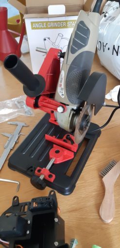
With some setup and care, it makes lovely orthogonal cuts in steel. How does it fare against the aluminium?
Pretty good as it happens. On the plus side there are no chips of aluminium littering the garden for my assistant to tread his paws in, like there was with the power mitre saw.

While faffing and putting up the new fence panel I was struck by a thought – how wide does the chassis _need_ to be? At the minute the width is governed by the servo box, which is in the way of a lot of things. I can’t put an extra gearwheel in to feed off the drive shafts in order to drive a turbocharger, and having a bit of space there would be a great place to put the Pi. There is a lot of servo box in front of the gearbox.
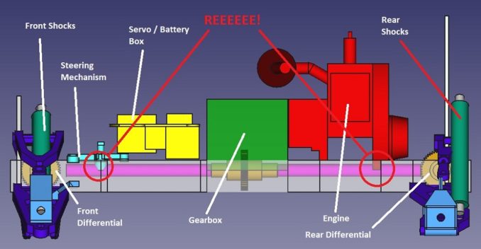
What I really need to settle the argument is an idea of how wide the front and rear diffs are going to be. Keen amateur Cnuteneers who have been following the series will know I have some 1/8th scale diffs clutched in my sweaty mitts, but no driveshafts. The idea was to just bung it in there and see what broke, but the 1/5th scale diffs were on special and they come with CVD driveshafts. That puts a whole new perspective on the design of the housings for front and rear drive trains if the width is wrong for the driveshaft length.
It will also mean that with the forever gears in place, rather than temporary stopgaps, I have a concrete idea of where the space will be which will mean I should be able to put some gussets in the corners of the frames. Clean ones though, filthy gussets will not braze well.
I am also considering using angle brackets internally after reading that a box section is not significantly weakened if you allow 1.5x the hole diameter of solid material around the holes. The holes could be 3mm, so that’s 4.5 mm either side which gives a total length of 12 mm. The box section is 15mm so that is going to be ok in x and y directions, not so much z but I can probably live with that. I think getting the second braze in to connect the third piece, the upright, is going to be a challenge to do without de-brazing the other joints and there is too much going on to do it all in one hit.
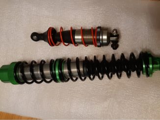
The front and rear diffs arrived and they are spanky spiral grooves instead of traditional orthogonal toothed gears.

Feel the quality of the presentation box!
More importantly, CVD joints so the driveshafts can be bounced up and down by the suspension and twisted left and right for the steering.

Unfortunately when assembled, the horizontal gap between the front suspension arms is not that big – about 31 mm as far as I can see.
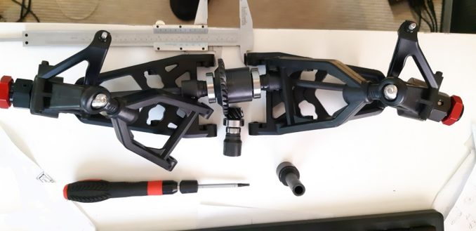
This is not a good thing, my plans were to have the chassis forward bars about 127.5mm apart which gives me a nice wide distance between the wheels, to offset the length of the car. Having the driveshafts this short is really going to make the width of the car too narrow and it will be prone to rolling, especially as the engine is quite high above the line of the wheels.
In true cnuteneering fashion, we shall disregard this, file it under “too hard to think about for now” and move on. I am hoping I can just extend the axles on the drive cups that come out of the diff, otherwise I have to find a way of extending or replacing the driveshafts.
One other thing is that the wheel hubs are for an HPI axle, 12mm inside diameter for the cup that connects to the driveshaft. These are 10mm axles so I bought a length of 10mm tubing with a 1mm thick wall. This should fit nicely between the driveshaft axle and the wheel hub and just need cutting to size and a hole drilled through for the cotter pin.
[insert your own waiting here, some hacksawing and drilling]
A quick once over with a hacksaw to give a flat tangent and a good belt with the centre punch and a lot of burr to remove and I am ready to go:
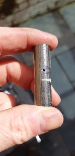
Nope, the outside diameter is _just_ over 12mm and the bloody things will not fit. I tried putting the bearings on the radiator and the tube sleeves in the freezer overnight to try and get them to play nice, but no dice.
Back to the tool foundry to make a custom rotary grinder:

They now fit the hubs but not the bearings. /throws sandpaper
And all this on the back of hours spent filing down a fat steel washer. On the plus side the gear change mechanism is done and dusted.
During the making of the gear changer, my Braheelian mate let slip that his CNC machine is not in an operable state and is not likely to be so for some time. And his 3d printer feed needs sorting. So I resolved to try machining the parts myself.
I am getting better at this FreeCAD malarkey and for a free bit of kit it is bloody amazing. Very easy to go from a mechanically consistent but visually confusing

To a proper blueprint like drawing at the click of a few buttons.
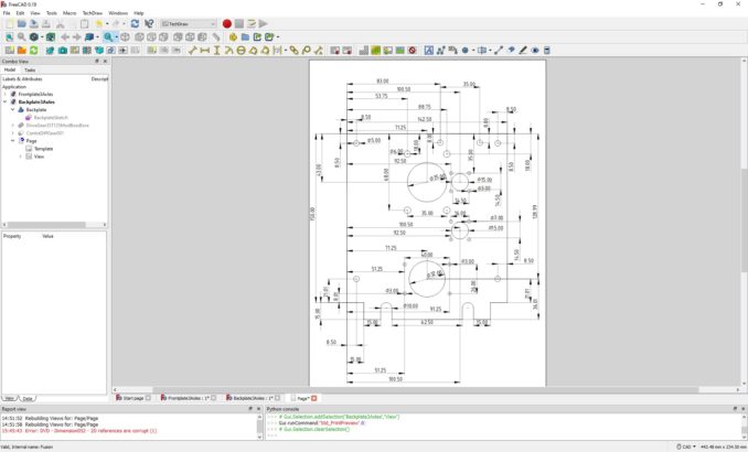
Firing up the FreeCad I put together a gearbox for the front / rear diffs and began cutting.

The step drill bit really struggled to get through the aluminium; at about 25mm wide a bore, the drill started giving off the Magic Smoke that means the engine is burning out. Hand drills like this one are not meant for low speed, high torque operation and that is what I need. As the step drill gets bigger, the part of the cutting edge that is in use has a higher effective speed against the material at the same RPM and it just skids.
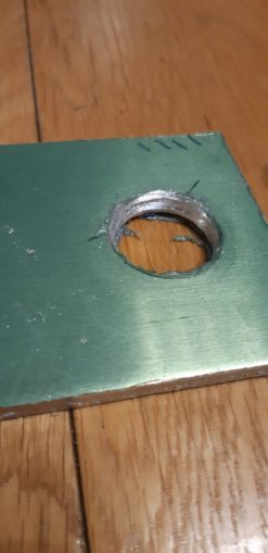
As you can see, the hole is just not big enough to fit the bearing into. Yet.
Chalk another one up on the Epic Fail board and the pile of “things too hard to think about right now” grows steadily higher.
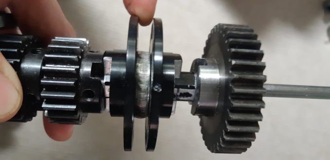
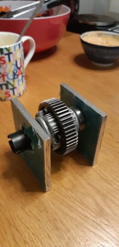
The last bit of cnuteneering left in this episode is to put the bushes into the gear that took so much trouble to arrive. The borehole is 8mm but my shaft is 6mm, so a bush is a little sleeve that goes between the two, a bit like the sleeves I made earlier. I just need to put a 5mm hole in to let the grub screw through and I am done.

I had to crush the bushes into the gear in my vice but managed to get 2 in there instead of 3; hopefully it is enough.

All in all, too many fails and not enough success.
Ah well, at least the dog still loves me.

Still waiting for:
Grease Estimated delivery: Apr 28 – May 19
Still left to do / think about
Finish Pi cases / breadboard / camera support
Test Pi on battery power away from home network
End point adjustment for servos and control mechanisms Dumbo RC setup https://www.youtube.com/watch?v=Sk6yh_Q2O6g
Petrol tank and centre of gravity
Test range of VNC connection to Pi
Where to house the Lucky Onion™.
How the hell am I going to cut the back/frontplate and gear housings?
Pics, vids, words and music © El Cnutador 2021
The Goodnight Vienna Audio file