Welcome back to Cnuteneering, where the possible is made more difficult by bone headed ignorance, overenthusiasm and pointy metal things being brought together.
You may want to refresh your memory on the project in:
Part One.
Part Two.
Part Three.
Part Four.
Part Five.
Part Six.
Part Seven.
Part Eight.
Design goals:
Fast as possible on offroad; too big to have on roads. I will set a target speed of 50mph.
4 WD.
Must be able to reverse, and brake.
Unbreakable, or as close to.
Must be able to mount GoPro or similar camera on it.
Cheap as possible.
We left the last episode of Cnuteneering at the exciting point of having the gearbox largely finalised, the control systems in place, a ghey horsie style central differential needing replacing and a race exhaust leaving the engine looking spanky.
About now I really do think I need to be putting metal together so I ordered some spanky aluminium welding rods from here.
These rods are allegedly great for aluminium brazing and can be used with a propane torch so I still don’t get my MiG welder. I am faced with a choice on how I joint though:
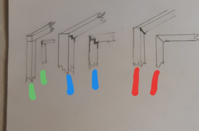
The green option is easy to cut accurately, blue quite hard but to my untrained eye looks strongest and red the hardest to cut right. Many thanks for the advice of the puffin welderologists ChickenELine, Stop it , Erection Knight for the idea of gussets, Pilgrim, grumpyangler who kindly offered machining services, Wildflowers and Bar Steward. General consensus that Red is the best jointing option when these need to be braised.
Next on the list of things to look at is brakes. While having each wheel with a separate brake disc and caliper would be awesome, it is also quite a lot of faff. I think if I can apply a brake to either side of the central differential, I will get all four wheels to brake at the same time, and I can adjust it so that the rear brakes are a bit more bitey if needed. It will stress the front and rear diffs though.
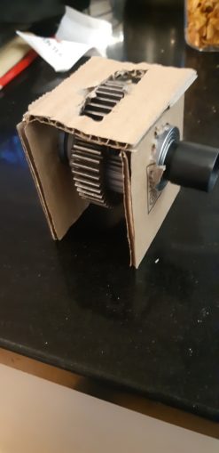
The basic idea is as below:
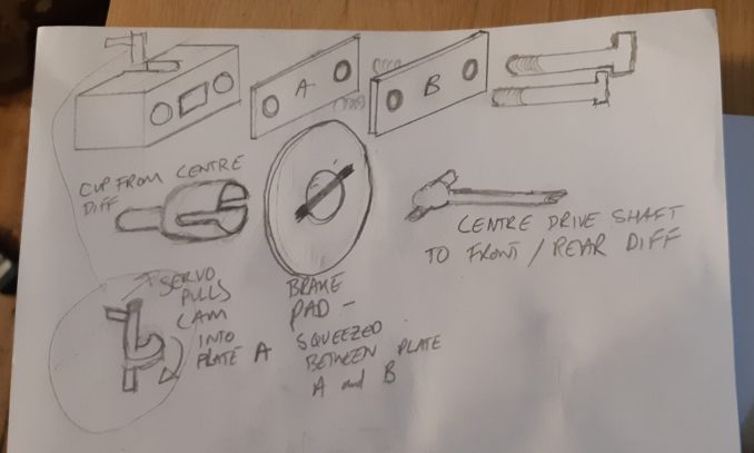
The brake disc is mounted on the drive cup coming out of the central diff, so it spins with the shaft. Above, there is a block with 2 pads, A and B that are free to slide on the two part threaded bolts holding them to the main block.
The tricky bit is the cam arrangement that goes through the main block – as it turns it pushes pad A into the brake disk, and then into pad B, squeezing the brake disc between the two pads.
Trying to find a small cam online was just about impossible, bear in mind this cam has to be about 10-15mm at it’s widest, and have a shaft attached. I may have to buy 2 HPI brake cams, but we shall see.
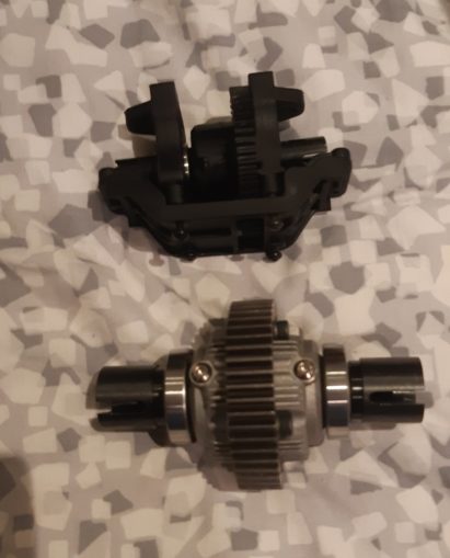
The big chunky central diff has arrived too, and it is quite the beast:
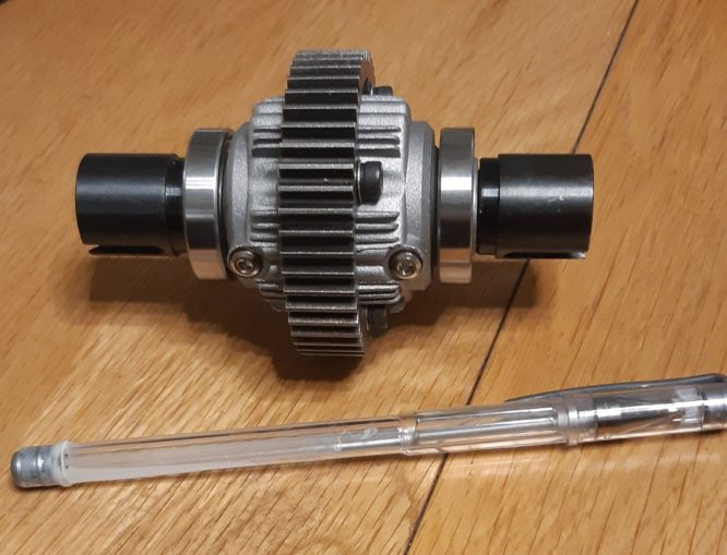
As far as I can tell, this is a helpful 1.25 mod gear size around the diff. I swear the rc car manufacturers use odd gear mod sizes just to drive you to use their gears instead of generic cheap ones in 1 or 1.5 Mod. Puffins paying attention will note that the last gear in the gearbox before the weedy central diff was 20dp.
After a great deal of faff, I finally sourced a 1.25 mod gear but with an 8mm bore instead of 6mm. I have also ordered a 6-8mm bush to fit inside which will need drilling out so the grub screw can pass through. All going well, paid around 4x the cost from Chy-Na only to get stymied midway through. BearingBoys contacted me apologetically saying their supplier was having trouble with their stock machine and my gear is trapped in it. So until a part can be sent from Chermany, I can’t get my gear delivered. A gear for a gear, so to speak.
I can make a case for it like below:
And mount the brake unit either on top, or below the driveshaft. I will hold fire on that until I get the gearbox all sorted out and work out just what sort of clearance I will have either for brake cables or rods.
On the plus side, this is much, much stronger than the previous central diff I had lined up.
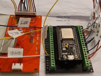
Focusing back on the killswitch, I have it all plugged in, and the lights come on in a pleasing fashion. The idea of a killswitch is that if the Rx loses contact with the Tx, the killswitch kicks in and stops the engine. It is also connected to a transmission channel so I can kill the motor when I want.
I had to take apart the engine to work out how it works – it shorts the magneto to earth.
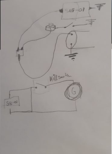
That is the theory anyway. In practice, there appears to be no change in output from the killswitch at all. If I switch on the Rx but not the Tx, I get an unhappy red light from the killswitch, but there is neither voltage nor connection between the output lugs (red and black line below, angry red light is the orange arrow).
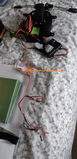
If I enable the killswitch from the Tx, I get… Nothing. Contacting the supplier, they are going back to the manufacturer to see what needs to be done.
Researching how killswitches actually work turned up something useful – I can use an old servo to turn my dead servos from cars passim into an on off switch.
I suspect the problem is that the channel I have the manual killswitch on only provides about 30% of “on” and the killswitch wants full on. Output from an Rx is done through Pulse Wave Modulation rather than a variable voltage or current, as I discovered when building El Cnutador’s ARSE a while back.
I can just use the electronics in a dead servo to turn the timed on-off-on-off square wave of voltage into an actual voltage that would normally go to the servo motor. Servo’s work by having a potentiometer measuring their angle of rotation, so applying voltage to the motor, the potentiometer turns.
If I take away all the busted gear linkages (these are the weak point on all servos that break when you crash), the voltage to the motor will stay full on regardless of turning. If I use the cables to the servo motor, I get an on / off current.
On this avenue, for now, let’s get back to my most popular theme so far, waiting.
I do have all of the front and rear suspension ready to go so I can assemble that at least to get an idea of driveshaft length. Unfortunately the front suspension is from an HPI Baja which is rear wheel drive only.
This has really ruined my day:
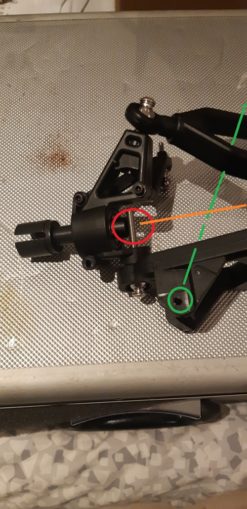
In red you can see where the bottom mounting bolt comes through the suspension arm and into the steering knuckle, only to be in the way of the wheel drive shaft (which is inserted from the wrong side in this pic, just so you can see the bolt better). The green dotted line shows how the suspension coil should fit through the top suspension arm and into the bottom suspension arm.
Which will be right in the way of the driveshaft to the front differential (orange line). Bugger, bugger, bugger.
But hey, this is Cnuteneering so I am sure some cunning plan will come to mind.
While thinking about the drive shafts, if I get some tubing of the right sort I can bridge from the weedy front and rear diffs to the chunky wheel axle cups, which are 15mm Inside Diameter (ID) and 22mm Outside Diameter (OD). The diff cups are 7 ID and 11 OD. So theoretically, a 15mm OD pipe with a 2mm wall will fit inside the chunky cups and outside the weedy ones. Put a 3mm bolt through each end and that is an el cheapo driveshaft made.
It turns out that on engineering forums there is a long fought holy war on hollow drive shafts vs solid. It would appear that a pipe of equal MASS is stronger than a rod is generally true, whereas saying a pipe of equal DIAMETER is stronger than a rod is flat out false.
So hollow driveshafts it is then, I can get a couple of meters of 15mm OD x 2mm thick ally tubing for less than a tenner. Engineering puffins are welcome to correct me on this…
I am feeling that the project is moving ahead nicely so I really need to be looking at how I measure the speed of the Cnutmobile when it is done. My phone driving GPS app, Waze, seems to be quite happy logging speed so perhaps I can write an app that captures video and also speed at the same time.
Given that I am largely blocked on just about everything right now I spend a bit of time learning to code – mobile phone apps.
It’s fucking horrendous is all I will say on the matter. A hot mess of event driven code where the main thread is run by the API.
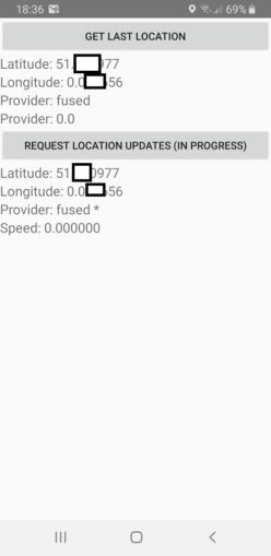
I did get this working
and a separate camera app:
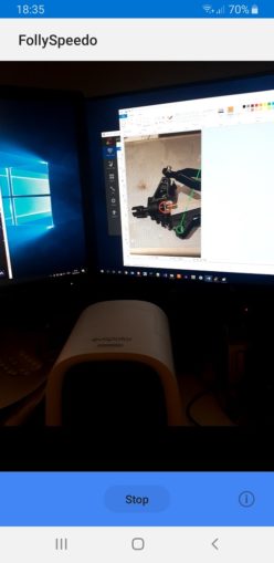
But trying to impose the speed reading as a text string over the image is beyond me. I just do not understand the entry points of the camera in Android and I do not have the patience to learn it, the video stream is never exposed to the API layer so I can monkey with it before it is compressed back to storage.
Plus as my ten year old son pointed out – do I really want my spanky phone getting oil, grit and grease all over it?
Turns out the Pi does support an el cheapo GPS unit. I bought one for less than a tenner, soldered it up and plugged it in.
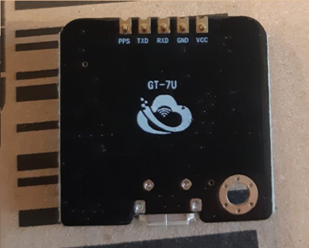
A little faffing on the Pi, and an anxious wait as it finally got a satellite lock after ~30 mins, and we are in business:
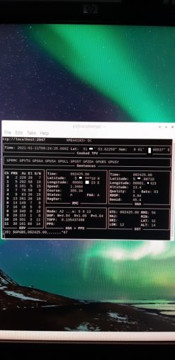
(some editing so as not to doxx my location there).
I am at least back in my comfort zone as avid El C followers will know from my efforts on the El C’s ARSE project. Back then I had a screen overlay which again is not compressed, it is just injected into the stream that goes to the display.
It seems that the Pi as well as Android likes to keep the video compression on the GPU and just let the CPU take a little peek at things without being able to modify it.
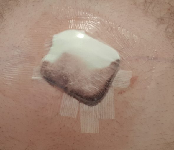
This should at least give me something to do as I am back to my endless waiting for parts. Not such a bad thing as convalescence is required following surgery.
On the plus side I can also start fitting more sensors to the car – an RPM counter on the engine, central drive shaft, engine temperature and so on.
As a backstop, if I can’t get the video to save directly with the annotations, I can always write a subtitle file on the Pi and overlay it on to the video later with FFMpeg.
Awaiting delivery
Grinder jig
Braising rods
1.25mod gear
Still to be designed
Reverse gear
Actual gear changer
Drive shafts from central diff to front / rear diffs and from front / rear diffs to wheels.
The chassis itself
Pics, vids, words and music © El Cnutador 2020
The Goodnight Vienna Audio file