
Welcome back to Cnuteneering, where the possible is made more difficult by bone headed ignorance, overenthusiasm and pointy metal things being brought together.
You may want to refresh your memory on the project in:
Part One.
Part Two.
Part Three.
Part Four.
Part Five.
Part Six.
Part Seven.
Part Eight.
Part Nine.
Part Ten.
Part Eleven.
Part Twelvety.
Part Thirteen.
Part Fourteen.
Design goals:
Fast as possible on offroad; too big to have on roads. I will set a target speed of 50mph.
4 WD.
Must be able to reverse, and brake.
Unbreakable, or as close to.
Must be able to mount GoPro or similar camera on it.
Cheap as possible.
We left the last episode of Cnuteneering at the cutting of materials, and the waiting for parts. Well, the parts arrived literally just after I had written the previous episode so there’s karma for you.
The parts are all in brightly coloured ABS plastic and smell a little bit vinyl-y. They have a stickiness that is quite unpleasant but it comes off after leaving them out in the sun for an hour and washing in warm soapy water. Just one hour in weak spring sunshine; ABS plastic is degraded by sunlight.
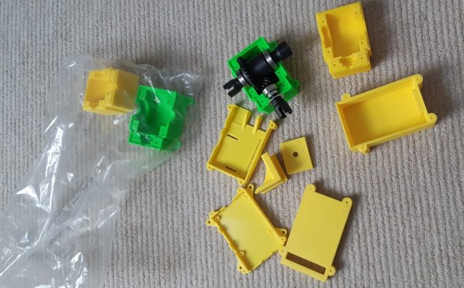
The thing I am most worried about is the gearboxes, which were about 40 quid in total, so about a tenner per piece. Each gearbox comes in 2 parts, the top and the bottom, and has some holes pre-made in them to take six bolts to pull the halves together. The idea is that the outer part of the bearings are gripped and do not rotate in the housing. Also critical is how far forwards the pinion gear is in relation to the spur gear. There is a little tolerance but more than a millimetre or so either way and the gears will wear unduly.
A little gentle filing of the edges and the gearboxes fit together snugly. Sharp eyed puffins will see there is a lip that runs around the edges that are to be butted together so that water has a harder time getting in. The holes in the bottom part were tapped with an M3 tap to receive the retaining bolts from the top half of the gearbox.
Putting the gears in was a bit of a struggle; I had measured the exact bearing width but not the small puff outs between the centre circle and the outer. This means that the bearing itself is constrained and chafes against the plastic wall, which is bad for the bearing and introduces unnecessary friction in the drive train.
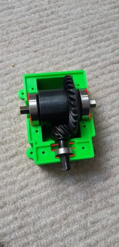
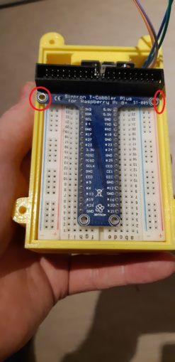
A short while of filing (OK, about 2 hours in total, it is fiddly in there!) and the two pieces fit snugly together with the gears in place and the bolts tightened. The red lines in the pic above show where I needed to file back to give the bearings free movement. I am bloody glad I did not go for aluminium gearboxes though; at 1800 quid instead of 40 to have them machined I would be spending a lot longer than 2 hours to file them back and would be fewmin. At least with the dayglow colours the bearings would leave a mark behind if a bit still needed filing.
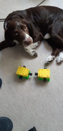
They are still quite heavy though, for plastic and a small bit of metal. But precious now, so I assigned a guard dog.
The outer edges of an assembled gearbox are straight 90 degrees as they are printed on a flat surface, with all the indented features pointing upwards. It has to be like this as the 3d printer builds from a flat plate upwards, depositing a single hot bead of molten plastic as it goes. These have chapped my soft office workers hands in quite a beastly fashion. One side effect of all the filling is that the fingerprint on my index finger has been eroded. Not too much of a deal until you realise that phones are unlocked with finger prints, RSA secure keys that I need to log in to work, banking etc are unlocked with a fingerprint…
On to the new case for the Pi, that has mounting holes and a case for the camera and for the breadboard.
First step is to clear down the breadboard of all ARSE project connections and just leave the GPS. I will connect the IR lights, temperature sensor and IR sensors when I have actually coded them in to the raspivid utility that I am going to use to save camera footage with GPS info embedded in the video.
This is probably the clearest I have seen the board for a long time.

The Pi fitted snugly into the new case which is in fetching Flight Data Recorder yellow. I thought it’d be easier to find in a field if it became detached from the car at some point. One thing that bothers me is there is very little ventilation to keep the unit cool. The car is going to be in mud and water at some point so I wanted as much protection from the elements as possible.
At this point it occurred to me that my design of piggy backing the breadboard case on the pi case was sound… If I had some 80mm M3 bolts. Which I do not have.
Fitting the GPS into the breadboard case I recall thinking – I need a pad coming from the wall to be able to mount the GPS unit on to it without the bolt going through the case wall. What I did not then think of was that the space taken up by the GPS unit would put it in the way of the breadboard.
If I put some short lengths of plastic box conduit in the bottom of the case, at least I get the breadboard elevated above the cables. It will do for now but the breadboard sits way too high for the lid to go on top.
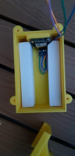
Oh but wait! Cruel fate and lack of engineering discipline have more treats in store for me. Even if I take out the plastic conduit spacers, the cobbler (blue / green T shaped thing that plugs into the breadboard) is in the way because I had measured the width of the breadboard not the cobbler.
I either redesign the Pi / Breadboard arrangement of there is going to be some _very_ careful hacksawing coming up.
Still, I did manage to Cnuteneer them together for now so at least I have a coherent unit that I can move about. I just need to fit the battery to the power input and see if it still works.
I set my phone to act as a wifi hotspot, and I have already configured the Pi to connect to that network. House internet switched off just to be sure, and fingers, toes, thumbs and eyes crossed in hope. The Pi has been switched on for a good half hour on battery power for now so it should have had time to see enough satellites to take readings.
I fire up VNC Viewer on my phone and run the video capture.
The help file is not particularly helpful on this front and the annotations don’t update unless some output is specified. Weird as hell, but not as strange as having to specify background / foreground colours not only in YUV colour expression instead of RGB values, but some lazy programming means you have to give them as VUY.
Now, given that white as YUV is hexadecimal 0xff0000 and black is 0x000000 if you reverse the order then white is 0x0000ff or just 0xff. Not sure how that improves things so much but anyway. Some further reading of the code and I end up with a passable command line that is impenetrable unless you have first Learnt To Code and then read the source for the raspivid utility. For some reason I can have background as any colour but the foreground is any shade of white. I am not going to waste any more time trying to get that working; the text is visible and that is largely what I am interested in.
The command I run is pretty involved:
raspivid -t 0 -a 1038 -vs -gps -ex auto -md 6 -ae 32,0x152b95,0x808000 -o cnutmobile.h264
Raspivid is a demo application that comes with the Pi that I have modified a bit for my own ends, adding more info to the GPS overlay output. This means I can extend this to include all the other sensor data when I get them working.
This tells the video capture to run until stopped, annotate black background with date time and gps, video stabilise, enable gps tracking, use auto exposure, select mode 6 capture which is 1280×720 and offers a frame rate of 40-60 FPS, annotate text fontsize 32; foreground as VVUUYY; background as VVUUYY, save the video to a file called cnutmobile.h264.
The h264 is raw video and not really very playable in many players so I will tart it up using ffmpeg later so it can be played on regular players.
The command line is a pain in the arse to type on a mobile phone so I just create a short script to run the above and make it easier to kick off the capture.
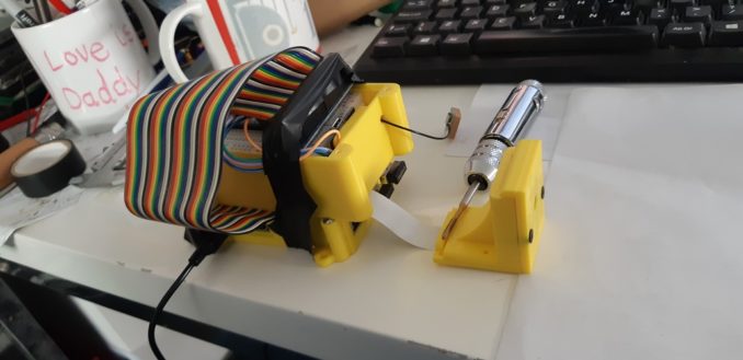
All of the bits are flopping around each other and the camera keeps falling over so I spend some _very_ careful time with a hacksaw and metal files. I finally get the devices playing nicely together in one coherent lump:
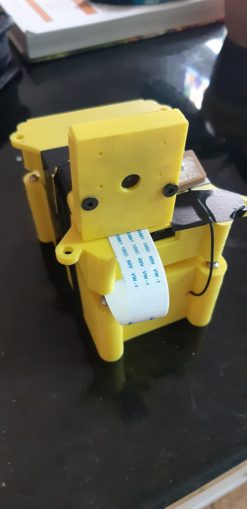
This means the unit is now one single block and can be moved about easily. Note that the antenna is ceramic side up, which is the way these things are done apparently. As I retested that everything was working when plugged back in, the unit began overheating so I think that the concern I had previously was borne out. A conundrum indeed, use it too long and the Pi will burn out, cut some ventilation holes and water / mud will short out the circuit. I look at the pile of “Things Too Hard To Fix Right Now” and wearily toss another on to the mountain.
One thing about the battery pack is that it does not quite juice the Pi as much as it would like and I get a “Low Voltage Warning” on screen when running mobile. That said I don’t seem to be getting temperature warnings either, not sure if this is because when mobile there is no monitor to drive or if the lower voltage is helping in this regard, but hey it is a win so I am taking it.
The battery seems to last about an hour from full charge which should be plenty for recording my failures when the Cnutmobile is up and running. I need to get some 3mm stud rods to properly fit the units together but I can wait (again) for them to arrive as I still need to plug the RPM counter components and temperature sensor into the breadboard. Oh and get them working alongside the GPS.
I need to test the range of the VNC connection when out and about; in my postage stamp sized garden I can wander to the furthest reach with the Pi in the opposite corner and still get a signal. This will be useful info to have. So if you were in a Marks and Sparks carpark watching a worried looking middle aged bloke looking at a suspicious yellow box on his car and his phone the other day, that was me. Range is about 70 paces so I would guess in the region of 50 metres or so. That is going to be most excellent.
At the minute the main worries I have about the car’s efficacy are the polycarbonate gear box shell being too weak, the gear change mechanism and how good at driving it I will need to be to change gear without shearing the gears and hubs into an expensive mess, and whether the chassis will buckle if I go over broken ground. Crash damage and repair is also an issue; as I decide how everything is put together I do not want to have to re-make the entire chassis from scratch just to fix a single broken element. I am not sure if the 6mm shafts the gearbox is built on are going to be strong enough.
Maintenance should be relatively easy; once built then the front and rear diffs won’t need greasing too often, the main gearbox is open to the elements (just waiting for a small piece of gravel to get caught between the gears and smash everything up) and the servos and radio gear should be easy to get at.
These things are but parts of the many, many problems and worries that sit on either the “Too Hard to Fix Right Now” and “I’ll Fix It When It Breaks” piles.
But the big worry is going to be getting the gear change right – if I can get it smooth then it will hopefully not stress the gearbox components too much. Now, the drive train comes from the engine via a centrifugal clutch. Until the RPM of the engine hits a certain point, the pinion gear from the engine is free to turn but is not driven by the engine.
So much the same as driving a car with a broken clutch cable (and no synchromesh but we’ll ignore that for now) I just need to be driving along in first gear, completely ease off the throttle so the centrifugal clutch disengages, and then change gear. The motion of the wheels will keep the gears turning, and the servo will elongate the spring that is pulling the gear changer along the guide. So the gear interlock will press up on to the drive interlock under pressure of the spring, with the servo straining at full travel to keep it there.
Once the interlock is engaged, the spring will return to normal size and the load is off the gear change servo. I can then open the throttle up again. Not exactly a F1 style high speed gear change but then again I don’t have a team of top engineers and a multi million pound budget. On the plus side, I only kneel to find bolts I have dropped on the floor. Going down from second gear to first gear is going to be interesting though as the car will be going much faster.
All in all I need to be able to see what is going on with the gear changer and this is why the range of the Pi is useful – I can see what is happening in realtime. Perhaps I could look into getting a boosted WiFi network card on the car and one for my phone or a laptop to increase the range. At the very least, the footage is stored on the Pi for later viewing, but you can’t beat a real time feed. This is also why the RPM counters are quite important too. I should probably add a gear mode sensor in there too I suppose so the gear state (1st, neutral, 2nd) is recorded as well. I have no idea if the Rx/Tx will interfere with the WiFi though but at least I can start the capture and view it later.
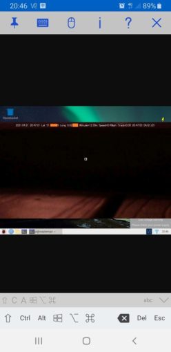
For now, I enlisted the aid of a sulky pre-teen and my car, she operated the Pi while I drove. There is no sound either so perhaps I should look into that as well, to hear the sound of pistons ramming through the engine block or the chassis disintegrating.
Martian style sky is due to the camera being an IR camera. I am some distance from my house so the Latitude and Longtitude are not blanked. I was very careful to drive at exactly the 20MPH speed limit (thanks Khan and Boris, you utter bellends) by the speedo and apart from a jitter of about .5 KPH the speed seems to be reasonable accurate. Obviously I will change the code to include the time only once, if altitude is important then there’s probably a very bad crash about to happen and I have no idea what “Track” is.
The important thing is that the Pi is bundled into something that can be strapped to the Cnutmobile and the telemetry is working as I designed it. This is a pretty big milestone in the project so far.
Still waiting for:
Grease: Ordered 3 received 1. The other two are hopefully on the way, but you never know…
Still left to do / think about
Cut down hex tube rider to the correct, smaller size
Rebuild the gearbox (again) but with lock nuts and threadlock
Go through the rear end design again so that the shocks and rear suspension arms are properly sited. This means I can finally attach the engine to the chassis
Sort out the car underside – at the minute it is just a gaping void
End point adjustment for servos and control mechanisms Dumbo RC setup https://www.youtube.com/watch?v=Sk6yh_Q2O6g
Petrol tank and centre of gravity
Siting of brakes
Siting of RPM counters
Build and install gear change mechanism into something better than the PoC that is there right now
Pics, vids, words and music © El Cnutador 2021
The Goodnight Vienna Audio file


