
Welcome back to Cnuteneering, where the possible is made more difficult by bone headed ignorance, overenthusiasm and pointy metal things being brought together.
You may want to refresh your memory on the project in:
Part One.
Part Two.
Part Three.
Part Four.
Part Five.
Part Six.
Part Seven.
Part Eight.
Part Nine.
Part Ten.
Part Eleven.
Part Twelvety.
Part Thirteen.
Design goals:
Fast as possible on offroad; too big to have on roads. I will set a target speed of 50mph.
4 WD.
Must be able to reverse, and brake.
Unbreakable, or as close to.
Must be able to mount GoPro or similar camera on it.
Cheap as possible.
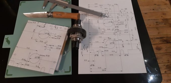
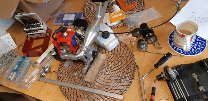
We left the last episode of Cnuteneering at the cutting things up and putting big holes in them stage. As the aluminium plate showed, my drill is not manly enough to really make a decent fist of cutting reliably, so I went with the polycarbonate to build the gearbox out of.
I had printed out the blueprint and affixed the drawing to a double thickness of polycarbonate sheet so at least when I drilled the holes through on my cheap shit drill press, they would at least line up with each other. Each hole was firmly centre punched, dead centre. And carefully, I have no idea how easily polycarbonate will shatter.
The two sheets were very firmly taped together which I thought would be enough to hold them steady. Physics had other ideas however – the spoil cut by the drill somehow got between the sheets causing them to part:
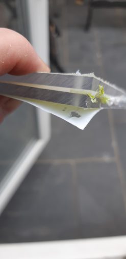
No matter, I could live with that by clearing the holes out as I went of spoil, a bit more faffing but the remaining small holes were drilled without incident.
Holes all happily drilled, I tried fitting the bearings and this went very well.
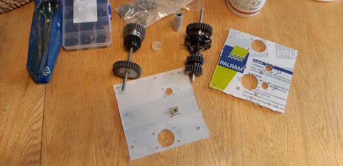
A nice snug fit, awaiting the making of covering plates that will hold them in place, to stop them sliding out sideways.
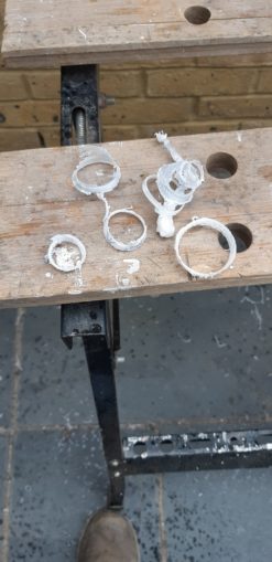
There was a lot of material to remove however, some of which had fused. On the plus side I can flog this to Reggie.
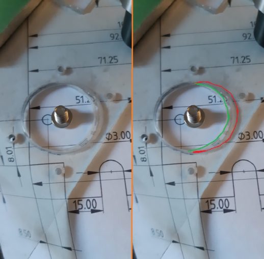
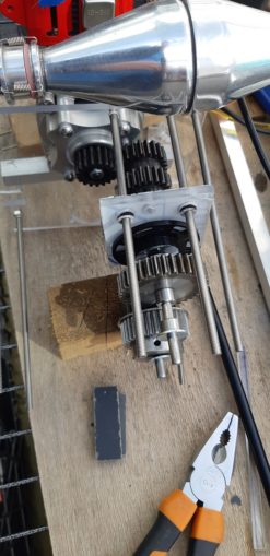
Putting the gearbox together for what would be the umpteenth time that day, it became clear that something was wrong.
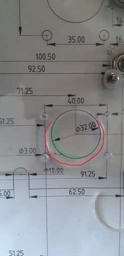
The green line is where the hole should end, the red line is where it actually does. I think that the additional pressure I had to exert on the press just to get the step drill bit through the material warped the angle on the cheap shit drill press and pushed it out. Arsebiscuits!
Luckily I had kept the big pile of art shavings and I was able to pack the hole out a little with an appropriately sized curl. Eagle eyed puffins will see that Instead of making whole plates to keep the bearings in place, a nut, bolt and 2 washers seems to do the trick. Less machining is always good!
I then taped off the polycarbonate and put a circle of thin card to hold it in place.
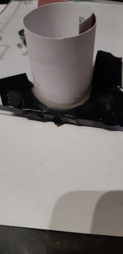
I filled the hole with epoxy glue, let it set, then turned it over and put some more glue in. Left to cure, it needed a little filing down before it is all nice and snug.
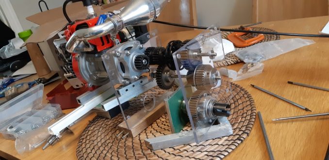
I could now get on and build the gearbox.
Which seemed to take forever but I got there in the end.
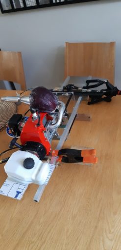
Looking forwards to the maiden voyage, I was contacted by a Totally Legitimate Businessman who for a small consideration, kindly sold me a Lucky Onion. Carrying such would guarantee at least 10MPH on the top speed, provide protection from crashes and improve handling.
All that remained now was to fit the gear changer and the gearbox would be complete! I machined the polycarbonate:
And fitted it
Sadly this is Cnuteneering. Pushing the gear changer from the top causes it to tilt, and bind on the hexagonal shaft so that it will not move. Filed again under “Too Hard To Fix Right Now”.
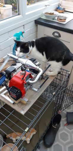
El Mewador thought so too.
This was not the end to my woe, either. While designing the layout of the gearbox backplate, I just had it in my head that the side channels would be cut once all the holes were drilled and I could size up where best to put them so the chassis frames can come through. The idea is to have a nice place to mount the gearbox to the chassis.
This works well, but in jiggling the gears around so that the last gear in the chain, the central diff was as near to the engine as possible while still allowing the drive shafts to go forward and back to the wheel diffs, I failed again as the gear wheel is pressing up against the chassis.
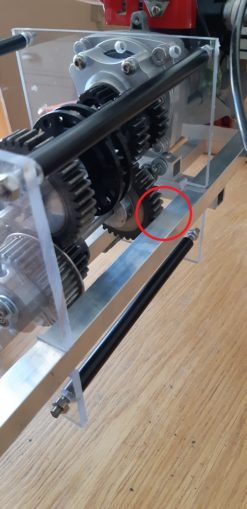
On the plus side though, the steering yoke looks like it will have clearance to connect to the servo and the wheels.
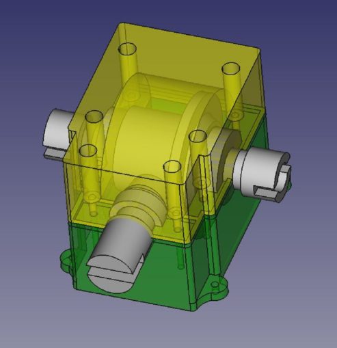
Having proved that I cannot realistically cut more than ~13 mm holes in aluminium, I had to abandon my plan of having an aluminium gearbox in place. So I designed one in FreeCAD.
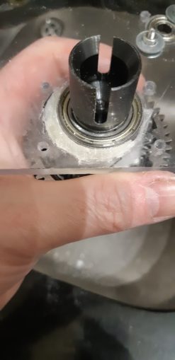
Being the tinkerer systemiser that I am I could not resist opening up a diff to take a look at it. This was also useful as I need to see if I can easily extend the hex bar that comes out of it. At the moment it is attached to a socket cup that the driveshaft will connect into and these need pushing out so the contact is wider than at present.
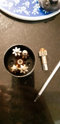
An interesting arrangement of the differential; I was expecting trapezium section gears in here. The moment of trepidation when I opened the case (inside a big Ziploc bag, just in case some spring or clip went flying) passed and luckily the gear was easy enough to reassemble after. However, there is no way to extend the existing shaft – it is a solid piece with the feeding gear.
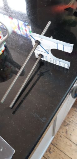
No matter, despite all my efforts to find a single piece of hex tube (instead of the 5 tons I could find) I settled on just getting a cheapo hex socket that will at least turn the hex into a square fitting that I can grind down some steel bar to fit, and extend that way instead.
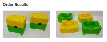
I used TreatStore to get the items printed, sent them Tuesday, printed Thursday (in the UK, about 15 miles from me) and still in the post as I type.
/shakes fist in postal
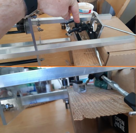
In a brief moment of clarity, I revisited the gear changer.
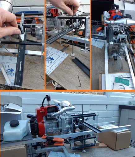
It is more moving parts, more faff and I will need to cut the long arm of the selector down to size, but it _works_ which is the main thing. I just need some kind of spring arrangement in there so that when the gears have not engaged, the servo is not pushing against something that cannot move (right now). I think if the servo pulls at a spring, it will pull the gears together and hopefully the channel / ridge will connect with minimal load on the servo.
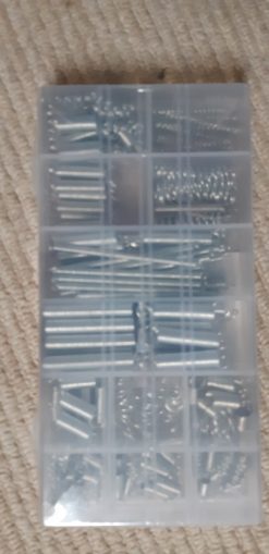
I can mix and match springs (200) on how this works.
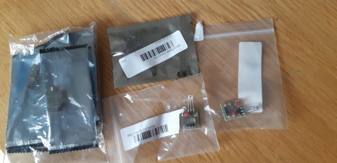
The telemetry parts have arrived, ready for integration into the Pi.
And finally, a happy finish.
Still waiting for:
Grease: Ordered 3 received 1.
Gearboxes and Pi 3d printed parts
Still left to do / think about
Test Pi on battery power away from home network
End point adjustment for servos and control mechanisms Dumbo RC setup
Petrol tank and centre of gravity
Test range of VNC connection to Pi
Pics, vids, words and music © El Cnutador 2021
The Goodnight Vienna Audio file


