Cnutelectronics [ ca-noot-elec-tronicks ]
noun
The art or science of making practical application of the lack of knowledge of pure sciences, such as electrical engineering, as in the construction of useful circuits without suffering any life-changing injuries.
Welcome to Cnutelectronics! It comprises the same bone headed ignorance, overenthusiasm, poor research, pointy metal things as Cnuteneering and also adds the additional danger of very hot soldering irons.
Having recently taken on the role of Armourer for my local fencing club, I am repeatedly testing swords and leads which is becoming so tiresome as it requires remembering what lines go to where and should they be connected or not connected if the sword is in touch with something.
It’d be much easier if I just made a magic box that you just plugged the sword or cable into and it told you what was wrong.
There are such things available on the market but they are about 50-60 quid and have basic functionality. I want to build a Rolls Royce tester that does everything. And in the spirit of Cnuteneering, I shall do no background research other than “this looks interesting and fun to do”.
Firstly, let’s look at wires and connections. Swords are connected to a scoring box and the scoring box has to work out if a hit on an opponent is actually an on target hit, an off target hit or a hit to an opponent’s pommel, depending on sword type.
Scoring boxes have three settings, one for each kind of sword – Epee, Foil and Sabre. Setting the box to the wrong sword type will lead to the box flagging a hit incorrectly and very often noisily when you plug everything in.
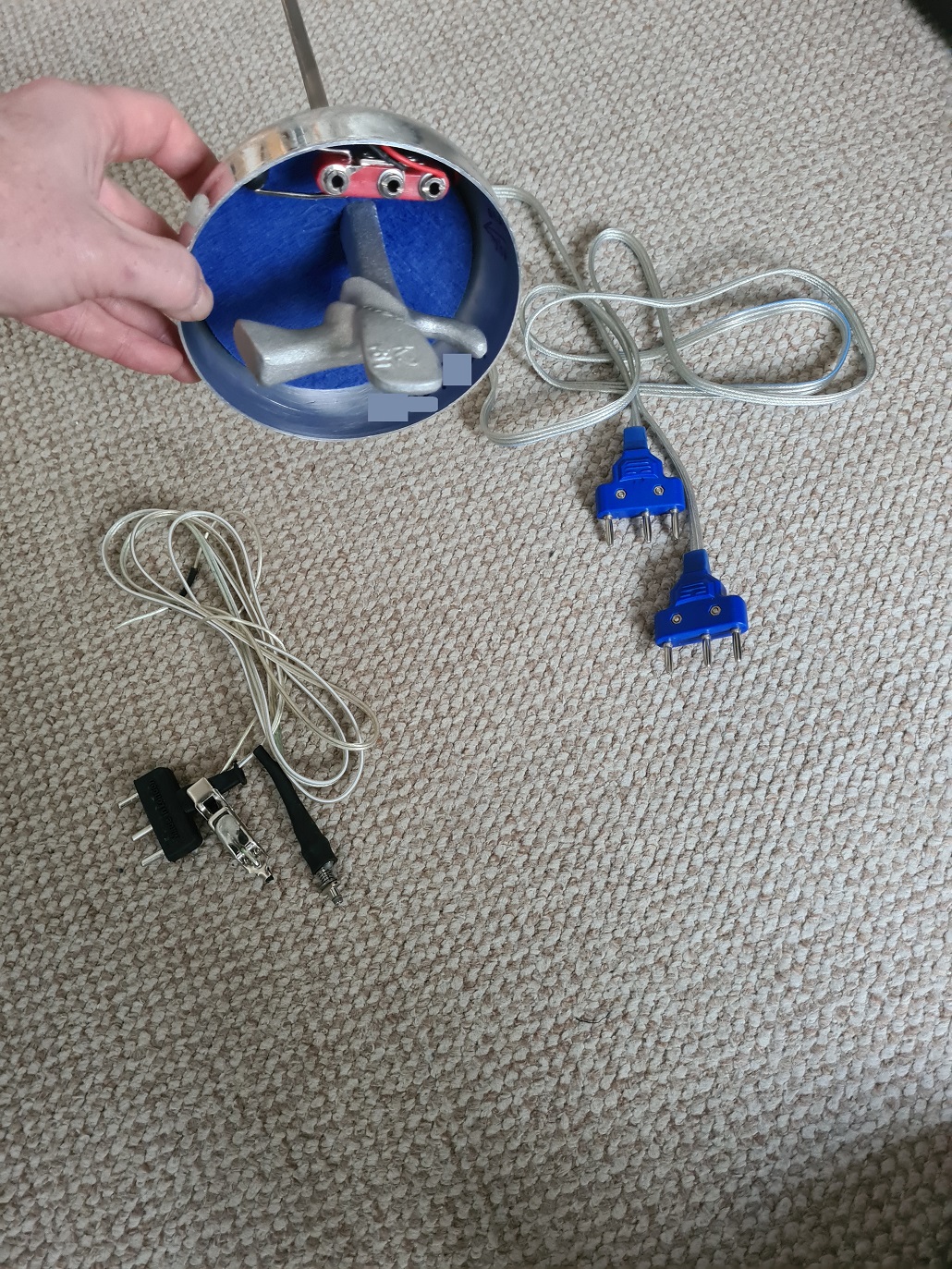
This is the holding end of an Epee blade, as opposed to the pointy end. At the top you can see three sockets in a red housing, this is what plugs into the lead on the right with the blue plugs. The body wire plugs into the sword, goes up your sleeve and down your back, where it is plugged in to the cable spool that goes to the scoring machine.
The cable at the bottom right is a foil lead – it has the same plug to present to the cable spool, but has a bayonet style fitting to plug into a foil socket. There is also a flying lead that clips on to the conductive lamé that foilists wear, like the big jessies they are. The body wire is the same for sabreuers, the cocky little popinjays.
From an electrical perspective this is how the body wires work physically:
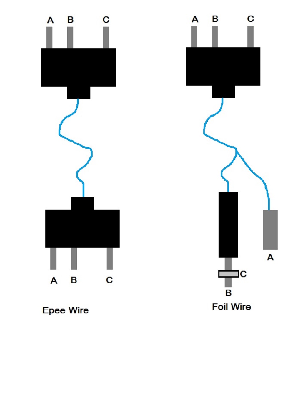
And then from a connections viewpoint, this is what we have:
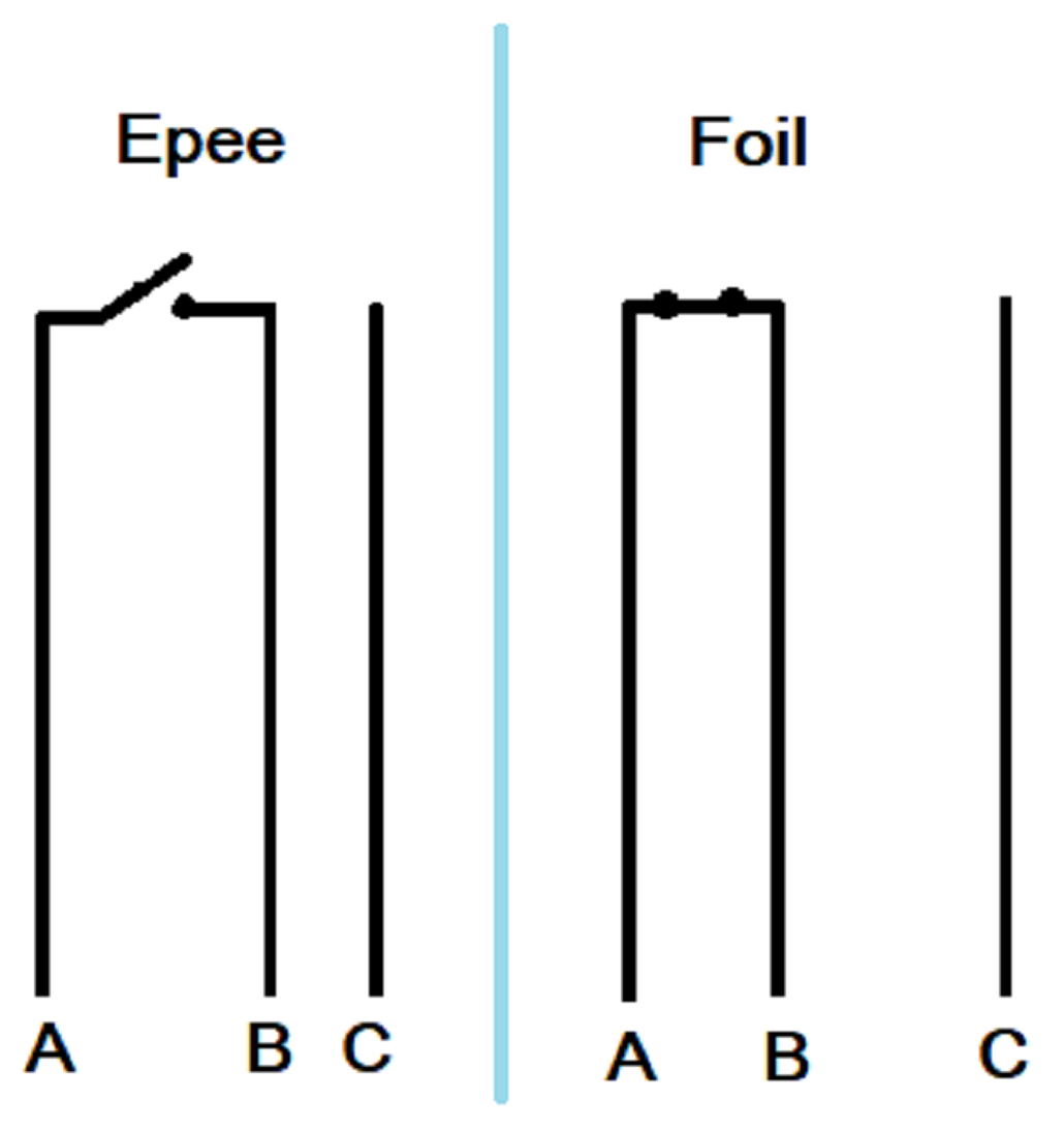
The button switch on the tip of the epee and foil work differently. Sabres work by making a connection between the blade itself and the lamé that sabreurs (the cocky little popinjays) wear so there is no actual switch.
The epee button switch is in the always open position, and closes when a certain pressure is exerted. The scoring box will monitor when this connection is made, and flag a hit unless you’ve hit your opponent’s pommel (which is connected to line C). A foil works the other way around, it is always closed until a certain pressure is exerted and there is a connection to your opponent’s lamé; the scoring box measures when this connection is broken.
So, that’s the science of it, we have to make sure that the body wire has good connections to the plugs at each end, and we need to make sure the connections between A, B and C are correct for each sword type.
This means the Blade-O-Matic must be told what kind of sword it is to diagnose, and then check to see if there are any incorrect connections between A-B, B-C and A-C when the point tip is at rest, and then again when it is depressed. A full writeup of how these things work can be read here.
Clearly what we’re going to need to change the sword type and show good/bad connections is a touchscreen. While researching the ESP32 stuff for the solar powered temperature sensor I saw that the ESP32 is capable of using an SPI interface to touchscreens. So clearly all I need is an SPI capable touchscreen and we’re good to go.
Once again off I trot to AliExpress… This isn’t going to end well, is it?
Turns out there are quite a few touchscreen formats out there, resistive and capacitative touch. Resistive you seem to need a stylus to activate – it actually flexes the glass on the screen a little. Capacitative is just a finger pressed down on the glass, pretty much like the screen on your phone.
Choice seems pretty limited but I find one eventually, that is the right size and has capacitative touch activation. I get it plus some cables to connect to the pinouts, of which there are rather a lot.
The customary wait ensues and I have this gripped in my sweaty fingers at last:

As mentioned before, there are a lot of pins on the screen end of the screen:
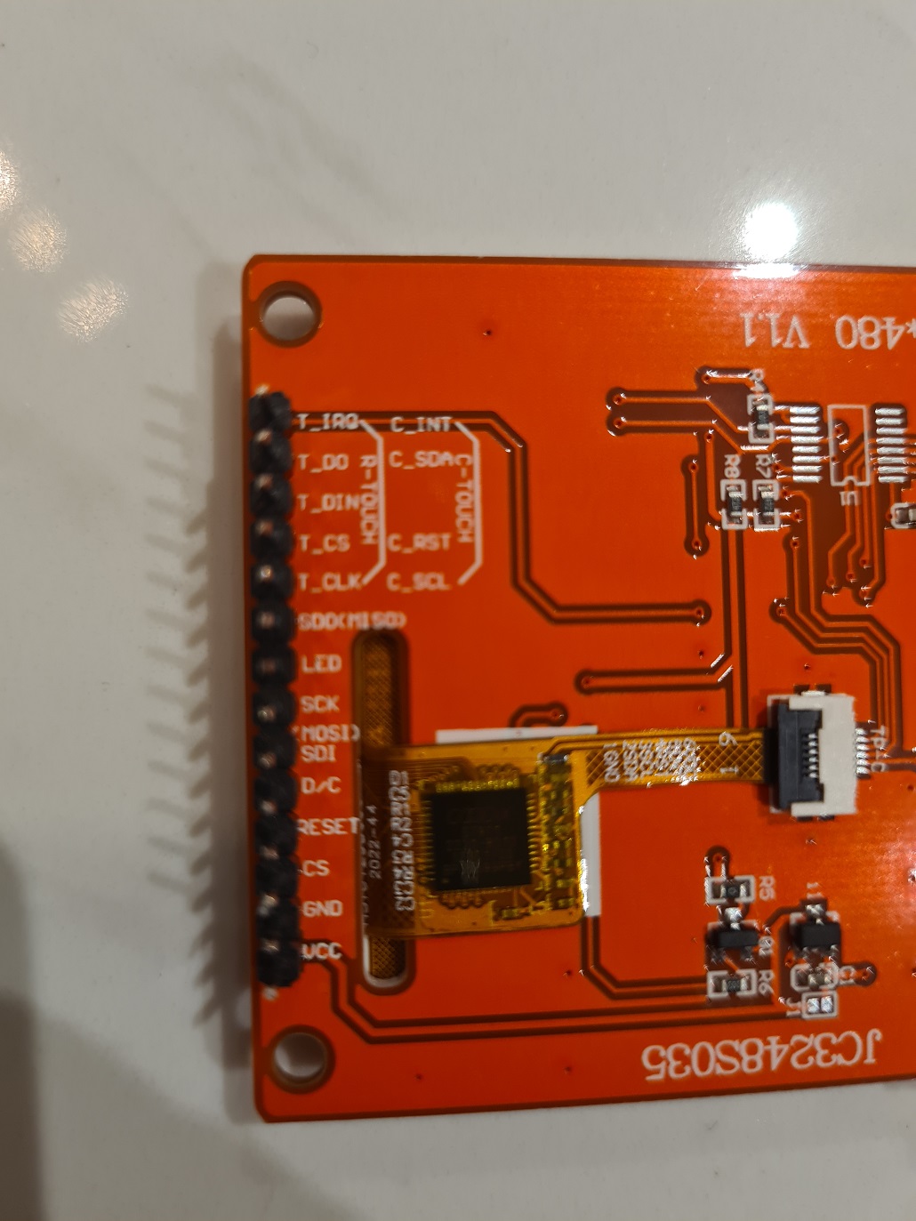
My soldering skillz are pretty m4d 1337 by now and I make short work of the connections. For some reason the screen end has pins, the SD card end just has holes. Luckily the bag of ribbon cables I bought has a bunch of the right kind of sockets.
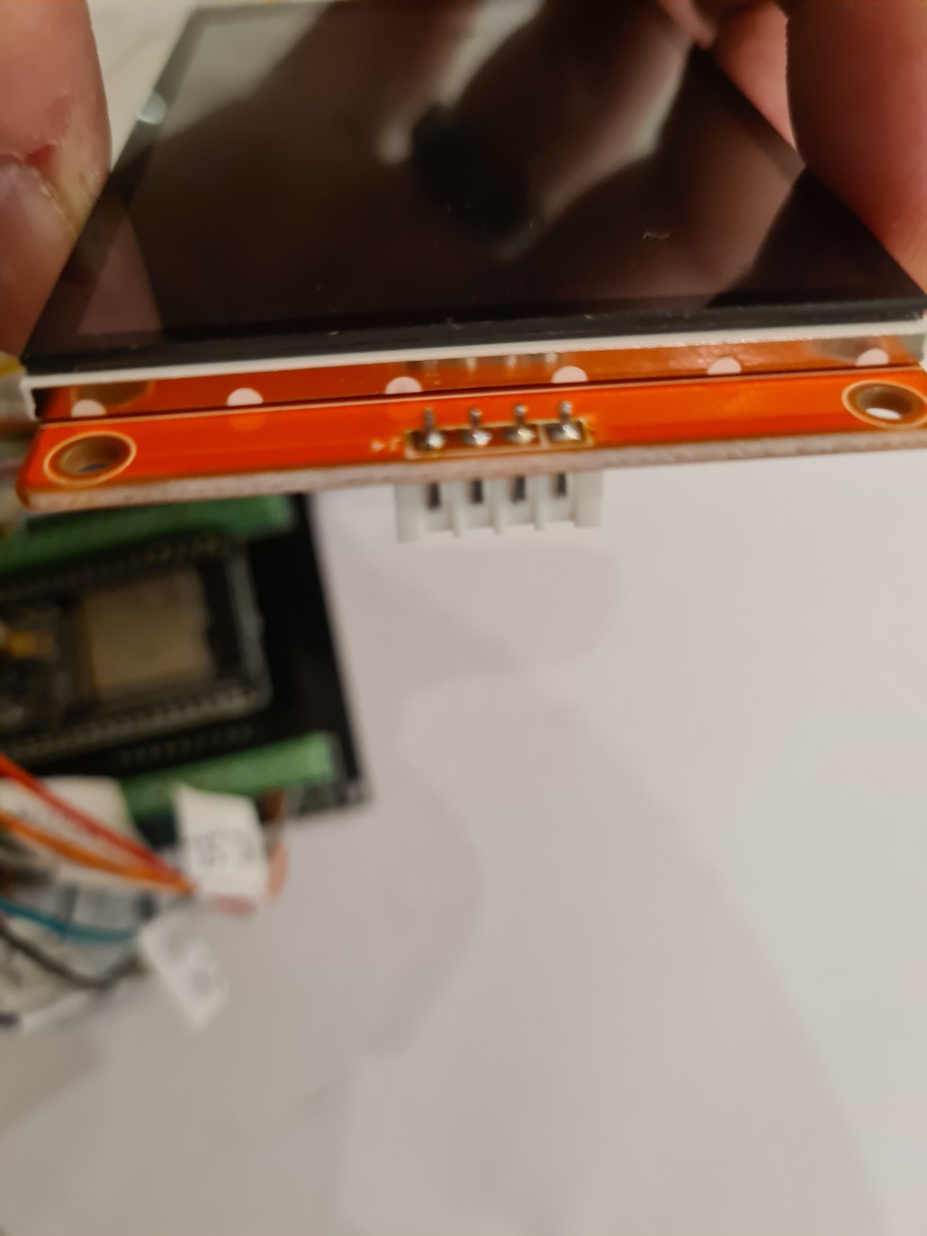
Soldering iron to ~350C, no more than 3 seconds in contact at a time and 3 minutes in between contacts if the first does not take hold. Clean the iron tip before applying it to the work with a damp sponge. I am really quite proud of this bit of soldering. Having bought a proper soldering station with a rest and a sponge I see why the pros have the sponge – having a clean tip on the iron really helps things along.

All soldered up and it is at this point I now realise I cannot read which pin is which on the SD card interface because the newly soldered socket is in the way, and I have no picture of the back of the screen that shows them. Let’s hope I do not need an SD card in the future…
With this amount of leads flying about it makes sense to label them. I have a big printout of the ESP pins to guide me.

It took a surprisingly long time to connect this many leads.

And so, I should now be able to just plug the ESP32 into my computer with a USB cable, and we’re off to the races.
Should just download a couple of programs from the interwebs, load them up and we’re good to go.
Nope.
One of the hallmarks of *eneering is I fail to do proper research up front and end up bodging stuff together, smiling through the tears and laughing at the blood. In this case that’s not really the case. Where you can see widget A is a bit too big to fit in Crevice B, a little judicial application of the Dremel or WD40 usually sorts the problem.
But in electronics, it either works, or it does not, there’s not really any inbetween state. If software does not work, it could be the hardware, or the connections in the hardware or a combination thereof.
I embark on a bit of learning and self education, and get up to speed on how TFT screens and ESP32 get along. It’s all done through an SPI interface which needs these specific pins to be connected, according to the webpage I bought it from:
CS – Chip Select
DC – Data Control
SCK – Clock signal
SDI/MOSI – SPI Data In or Master Out Slave In
SDO/MISO – SPI Data Out or Master In Slave Out
Trying to get an understanding of how SPI works I just looked up what MOSI means in the real world only to find that wokery has infected the snowflakes at Open Source Hardware Association where the usage of the master / slave model is now triggering them and new acrotheys (previously acronyms, too redolent of the patriarchy now) are to be used. No one has told the Chinese it seems so I have to translate from Woke to Normal when reading docs.
The upshot is – SPI uses the clock signal to keep things synchronised, the ESP32 is the master and will push data via the MOSI line to the screen. The SPI devices can be chained which is where the CS line comes it, which actual SPI device should I be talking to? And should I send data or control signals? (DC). The information provided by the supplier is all contained on this page and this page only: so there wasn’t exactly a comprehensive manual to go with the device.
The above took far longer than I would have liked, autocomplete in my compilers has made me weak.
The chipset on the TFT is apparently the common ILI9488 which seems to be well supported. Some techno genius called Bodmer has a giant library https://github.com/Bodmer/TFT_eSPI that will do all the faffing about at the chip level for me, and provide some useful primitives like “write text at position 10, 20 in green” and “set background colour to black” and so forth.
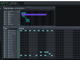
There is also some useful stuff on how to wire things correctly in the repo, so after a little mucking about, I get this test program up and running:
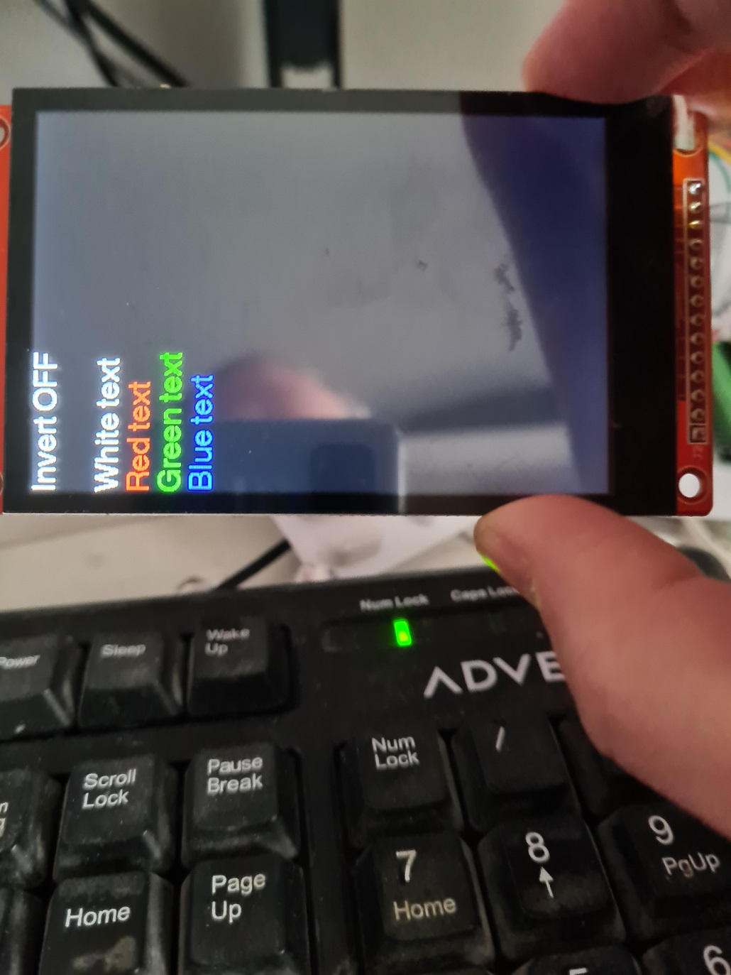
Next up – get something better than “Hello world” on the screen and integrate the touch screen capability.
© El Cnutador 2023