
Welcome back to Cnutelectronics! It comprises the same bone headed ignorance, overenthusiasm, poor research, pointy metal things as Cnuteneering and also adds the additional danger of very hot soldering irons.
If you missed them here are the links to the first and second episodes.
We left the last episode of Cnutelectronics where pretty much all of the soldering is done, and I have 2 completed circuits – the rechargeable power supply and the ESP32 mess of screen and sockets.

Now, I need to get all the bits in the box, so to speak. For some reason the project box I have has little standoffs presumably to mount PCBs on. These are no use and are getting in the way so it is time for some Dremel based filth.

In the picture above the red circle shows the standoff and the green shows the standoff cutoff. Would have been quite awkward to do with any other tool, /holds Dremel up to the light like a firstborn.
With the standoffs out the way, I can drill the pilot holes for the big holes I need to cut in order for the sockets to mount into. It is very tight in there so I hold the socket in place and mark the outermost hole by putting a drillbit the same size as the socket hole through the socket and rotating it about a bit to make a mark.
This has to be done from inside the box so that the height of the socket holes is correct. I have no accurate measurement of the depth of the plastic at the bottom of the box so this should make sure the holes are in the right places.

I get the first hole drilled out to 8mm and can then push a drillbit through the socket and the hole to hold the socket steady to mark out the other 2 holes before cutting from the outside.

That is the “main” socket which the body wire will plug into, and the “return” socket nicely affixed. I now need to attach the 3rd socket, for the bayonet end that is used for foil and sabre blade connections.

Making sure the sockets are mounted sturdily is going to be important as these are going to get a hammering if I get another pile of 15 leads to test. At least now I can solder the sockets and wires with the LED lights on. I Dremel off the extra bit of steel on the bayonet socket and try to solder on to the remaining lug but to no avail – just cannot get the steel pad hot enough to take solder, and my mini gas torch for chefs will just melt the plastic housing. So I attach a blade connector and jam it between the steel mount and plastic housing.

To mount the epee sockets to the case, I need some angle brackets. I have some leftover 20mm box section aluminium and hacksaw it across opposite corners to make the L shape I need. Initially I drilled just one side for the bolts to go through into the pre-tapped holes in the socket case (in yellow circles) below. I could glue them but being able to take them out is going to be better I think, too fiddly to resolder in situ.

Astute readers will make a correlation between how sharp the edges of the brackets are and the number of Elastoplasts on my fingers. When I was drilling one of the brackets, I was just holding it down with my hand on a bit of spare wood. I had forgotten how metal bites the drill when the drillbit first breaches the other side and paid the price. One massive cut across the pad of my index finger and another down the side of my index finger. I was lucky it did not shave the side of my fingernail off as well.
Sadly the bolthead is too large to fit into the hole straight and level, so I try to grind the bolt head down so it does not catch on the adjacent face of the bracket.

This was done by holding the bolt in the chuck of a hand drill (Makita, Grrr!) and having it rotate slowly while I applied the Dremel to the bolt head. Top bolt is untouched, bottom is ground down.
As ever, I was sooo very close to getting it to fit, but I needed to take a little too much off then bolt head and that would have left the hex socket too weak to apply any tension to. So I had to cut the bracket again to provide a channel for the bolt head to sit in.
I also cut a hole for the switch to be mounted through.

Finally most of the hardware is now mounted. The green box is the “main” socket and goes to the ESP32 as well as the live supply from the switch. The cyan box is for the bayonet socket, as yet unattached, and the yellow box is the “return” socket. The orange box has a bolt with a couple of nuts on to receive the crocodile clip from the foil or sabre wire. The scratches around the switch hole seem to be highlighted in this light, it is the first I have seen of them too!

As seen from the rear of the box, if needed I should be able to remove the switch, and both epee style sockets if needs be. I still have no idea how I am going to mount the bayonet socket though. One thing I did learn from Cnuteneering is never to affix things where they cannot be removed easily. The exception here is the brackets which I have impact adhesived to the project box wall, no other way of doing it that I can see.
Before I start attaching the ESP32 and the screen to the box, a little testing is in order. I plug in my 3.3v power from USB device to the LED circuit to test the blue socket lead you see on the right of the picture.

This is all well and good as the USB power supply is quite meaty but what I really need to know is will the battery produce enough juice to run the continuity test? I wire it in and then test:

At the moment I have to leave the battery supply unconnected as it will try to power the ESP32. This is a problem as when I program the ESP32 it needs to be connected to my PC via a USB cable, and it will try to take power from there too which will be bad I imagine.
Now that I can actually plug stuff in, it is time to start testing the tester so to speak. I will probably disappear into some kind of recursions here if there is software testing to be done as well, testing a test for testing…
The UI workflow to the BladeOmatic will be as follows:
1) Select the blade with the button.
2) BladeOMatic will immediately check for shorts across the 3 wires
3) It will now wait for the same blade selector button to be pressed to run the next test, or if it is a different blade selected start again at step (1)
4) Run the sword tip test – is the switch working?
5) It will now wait for the same blade selector button to be pressed to run the next test, or if it is a different blade selected start again at step (1)
6) Run the tip-shorts-to-ground test
This is starting to look more like a work project than a fun hobbyist outing so it is time to ignore the Gantt charts and focus on more important matters:

Step 4 sword Tip test cannot be done by just checking the sword tip connection, it needs to poll over a few seconds and reflect the changes in tip state. It’d be a mad scramble to select blade type and then press the tip all in one go which would be most undignified. So over say 5 seconds, it should examine and report the tip state.
There now follows some old skool buggering about in code as even if the text box for tip state is updated, the screen itself is not. The testing code is run from the main program loop, so I find out the hard way that calling the “UpdateScreen” function from the “UpdateScreen” function quickly overflows the ESP32 processor stack and crashes the unit.
There’s now more buggering about to get the tip test running in a background thread so there’s a separation between updating the screen and running the test.

I get this working and now I am seeing some artifacts appear on the screen for no reason. I try setting the text box to all spaces, all spaces in black but nothing seems to work – I still get the smudging. I try making the text box smaller then larger in the UI designer that comes with GUISlice and that seems to work, which is a result.
As part of this testing though, I am getting unreliable readouts from the pin. Turns out that a pin has 3 states, UP, DOWN, and WHOKNOWS. I may have made that last one up, but it is the case that background electronic noise can interfere with the reading unless the pin is drawn from a FLOATING (uncertain) value to either UP or DOWN. Luckily, the ESP32 has integrated pull up and pull down resistors on a number of the pins, so I shuffle the connections about a bit and tell the ESP32 to have the pins connected to the socket as PULL_DOWN.
Except this does not seem to work.
A fair bit of swearing goes by and then I find an obscure comment on a forum somewhere – once a call to analogRead() to read the voltage level from the pin is made, the pull up / pull down resistor is disabled and needs to be re-enabled before making an analogRead() again. FFS!
Some code changes to keep telling the ESP32 to pull those pins up, and we get a little more happiness going:

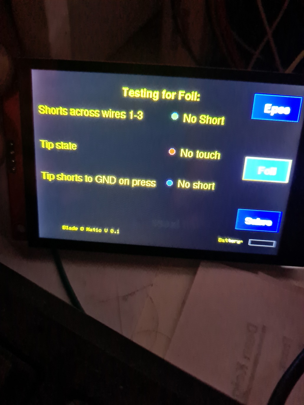
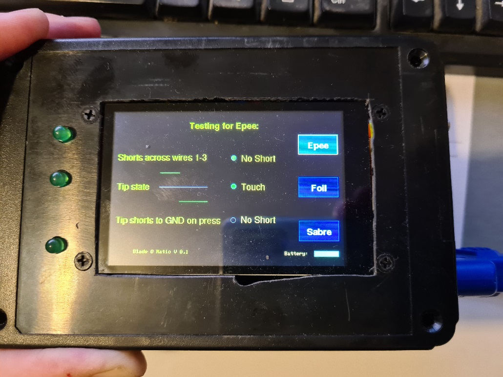
In the first pic you can see the middle test, “Tip State” is running. The “No Contact (4)” text box is counting down from 5 to show that the test is ongoing. With 2 seconds left, the middle picture shows that the tip has been pressed and there are 2 seconds remaining on the test. The last picture has now run the top 2 tests and each test was good so is set to green.
In this last picture the short test has passed (green) but the tip test has failed (red) and the Tip shorts to Ground test has yet to run (blue).
Next up I need to put a square hole in the faceplate.
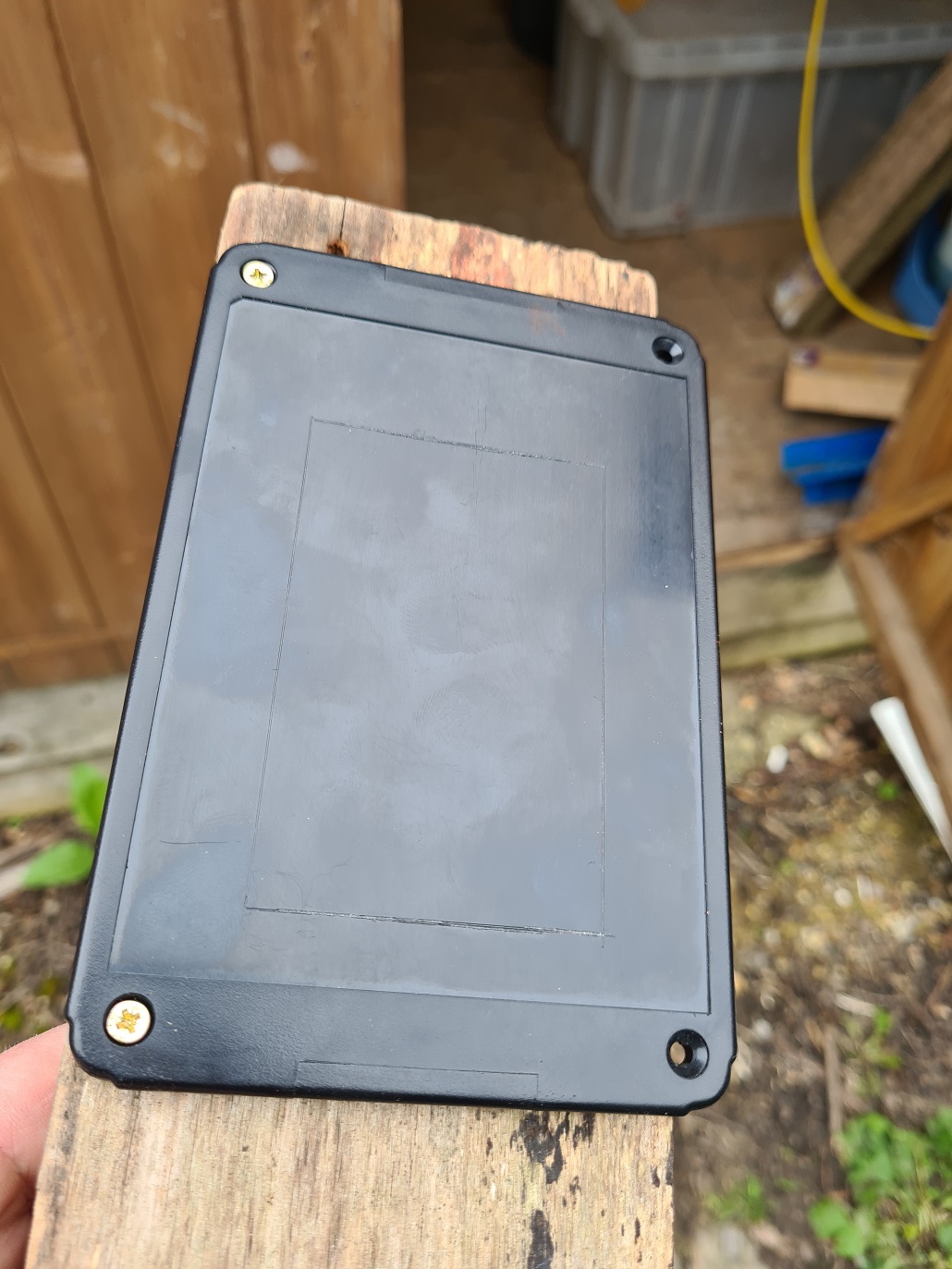
And now for the cutting. Observant puffins will know what is being used at this stage…
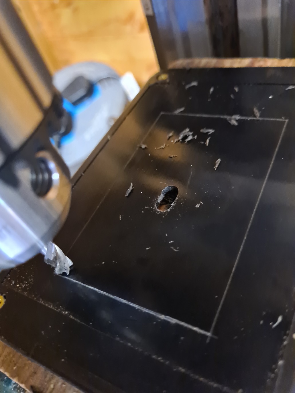
Sadly as ever the execution is somewhat lacking, there is quite some drift in the cutting here. I will have to find something to fill this in.

Now to make the holder for the charging port. The socket is mounted on a PCB, but there are no mounting holes on the PCB itself. So I cut out a shallow, long channel and a short deep one so the metal surround of the USB port butts up against it and will stop the PCB sliding if it is held in place.

I drill and tap on each side and put a bolt through from the outside.

The bayonet socket was drilled and tapped twice and I cut down some bolts with the trusty Dremel so they go just past the steel case. Everything is mounted and I can now feed the ESP32 and test circuit from the battery.

A final test – does the charger work?

Here we can see the charging light is red as the battery is charged up, then blue as it is fully charged. Luckily the clear polycarbonate lets the light shine through so you can see the charging status. I am taking that as a win, even though I did not design it with that in mind.
And here we have it, fully powered by the battery, with a snazzy custom built graphic to chart the connection strength when the tip is pressed, you can see it going from high to low just to the right of “Tip State”.
In summary:
Total cost – probably about 50 quid in parts I think. But a lot of fun to build, it will save me time in the future and I learned a hell of a lot more than I would have liked. Many thanks to leopard, Verax Cincinnatus and others who answered my endless questions.
And after all that effort, I shall be more like El Meowador.
As the weather improves, I can feel some Cnuteneering coming on. However, there is the small matter of The Cnuteneering Home For Wayward Lathes and Mills to establish…
© El Cnutador 2023


