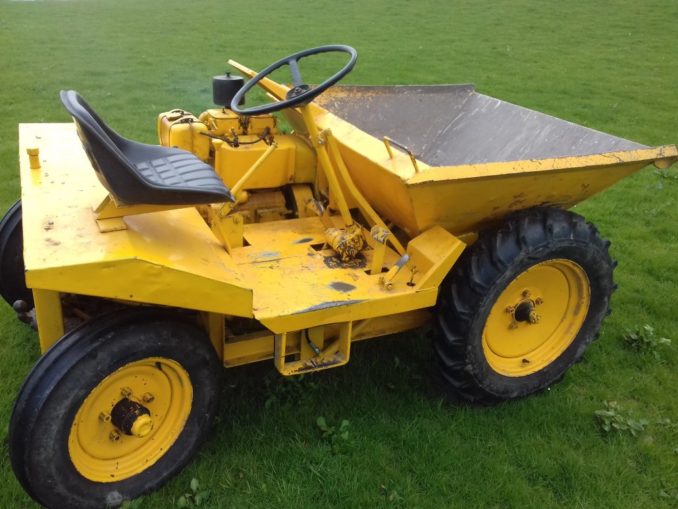
This dumper, one of the first types to hit the scene has no hydraulic system and the skip is basically unloaded by pulling a big lever which releases a hook and the entire skip rolls and tips forward aided by a slightly over centre pivot mechanism and forward centre of gravity. The contents drop out, in full, like it or not, then you must reverse a few feet to clear the mound and get off to return the skip to upright manually. All very well and a thousand times better than a wheel barrow, but I have a gravel farm track that regularly develops potholes so you ideally need to drop a dollop of fresh gravel at various points and this is a task that the dumper obviously can’t perform. Again, common sense would say that I should simply buy a newer dumper with hydraulic tipping, but I wondered about retrofitting hydraulics to my old one.
Initially I drove down to Dover to look for an asylum seeker landing on the beach. I thought I would employ an engineer to perform the job as the government tells me that these people are mostly engineers, surgeons and rocker scientists. I was unlucky as I didn’t find anyone so It was therefore back to the drawing board, I’d have to undertake the task myself. A study on Google images looking for inspiration didn’t help as much as I hoped for as all modern dumpers seem to employ small fat rams right under the skip working at a mechanical disadvantage and therefore imposing large loads on the skip and structure used for mounting. It appeared to me that the skip didn’t have the structural rigidity needed and there was also a distinct lack of room or obvious attaching points, so I moved onto plan B. Plan B, which was entirely my own idea was to use two long rams, one each side arranged to push the skip from nearer the top and thus operate at a mechanical advantage closer to unity. I marked off some points on the skip and dumper chassis and with the help of an extending old car aerial I did some trials to asses clearances from surrounding structure and the travel needed to push the skip forward enough to properly discharge. It was looking very possible but would rams be available with the dimensions that I was looking for? They would also need to be double acting rams too, so they can push as well as pull and thus return the skip after discharge. I found a good online hydraulic component supplier and started to study their stock. The size of ram was available, 755mm closed length and 1355mm extended and the smallest diameter with these dimensions was 32mm bore with a 20mm rod, these might fit the bill. Two would be required. Some sums; these rams are rated at 200 bar (say 3000psi) max working pressure so a 32 mm bore would equate to 8 sq cm or 1.25 sq inches and at 3000psi gives each ram a near 2 tonne push, Im afraid my brain really only runs smoothly with imperial units when it comes to guestimations and rough calculations, ‘bar’ for pressure and square millimetres are harder units to work with I find. So 4 tonnes in total and a little over half than on the return pull as you have to subtract the area of the rod from the area of the piston. No more maths required there for a skip than would just about hold one tonne if piled high. A smaller diameter would have worked well too but 32mm was the smallest available I guess due to strength and the potential for bow. I duly ordered two of these rams, and selected the sort with pin mounting holes at either end as I determined they would be most adaptable for DIY cobbling up a mounting system.

Just before we move on, I did a little research regarding the word ‘fescalised’ and this is what I found: “Its not in the English dictionary as it comes from the Greek word fescalise which basically means ‘without cheese’. Greek shepherds used the phrase ‘fescalised portion’ to describe the ‘shaft’ of a goat’s penis (a delicacy in Greece) which was held between the thumb and forefinger while the ‘helmet portion’ was dipped in a jar of Feta (or Philadelphia light) before being eaten…….”
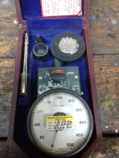
Now, back to business and onto the hydraulic pump. It was clear that one needed to be selected that would deliver oil at a sufficient rate to tip the skip in a timely manner, not taking too long so as you feel the need to break out the sandwiches, nor too quick so as to launch the skip content into orbit. OK, they are rather extreme examples but you get the idea. The first job was to calculate the volume of oil needed to fully extend the rams. Volume of cylinder, easy stuff, Old Trout was not needed for this and it came to almost exactly 0.5 litre, multiplied by two rams so one litre. A perusal of the pump section of my on-line supplier indicated that a regular ‘’gear’’ type pump would be fine and also the cheapest, but pumps were classified as Type 1, Type 2, Type 3 etc so what on earth was all that about? That was an easy mystery to solve, it simply reflected the physical size of the pump casing and oil delivery rates within the same group were varied by the size of the pumping components contained within. It appeared that the pumps needed to run at 500rpm as a minimum and 3500 rpm maximum. So, I better check to see what sort of output speed range that the tail shaft on the engine delivered. I have an old Royal Naval hand held tachometer purchased many years ago from a military surplus shop advertising on ebay. It has a three speed gearbox built in and can work in the range from zero to 50,000 rpm.
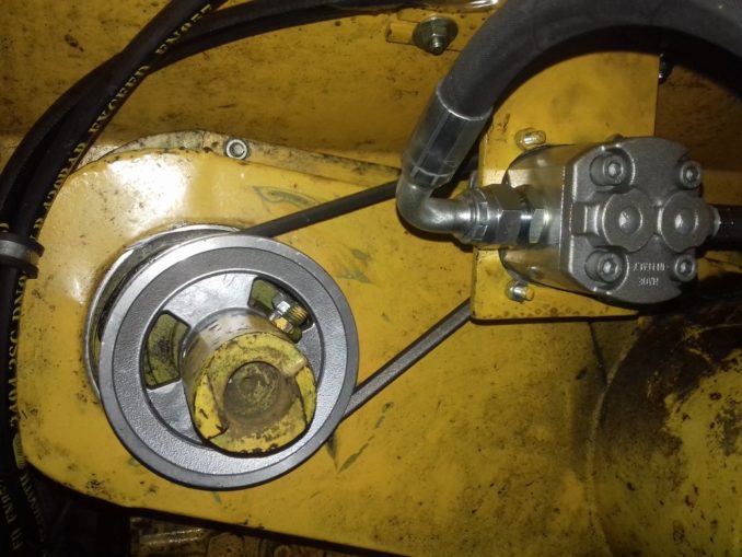
Tickover appeared good at about 500 rpm, as 250 rpm indicated on the camshaft driven tail shaft and maximum revs were 2200 so 1100rpm on the shaft. To me that indicated that a step up drive ratio of 1:2 should work fine, keep the maths simple and the pump operation within the suggested operating band. Should I drive it via a chain and sprockets or use a belt? I rather fancied using chain and sprockets but chickened out and decided upon a belt, working on the assumption that if things screwed up then the belt would hopefully slip rather than things destroy themselves via an unforgiving chain drive. Two suitable light alloy pulleys were sourced from another supplier with solid centres that would need machining to suit the drives. The pump capacity still had to be decided and again the calculations indicated that one of 3.2cc/revolution equated to 3.2 litres/minute at 1000rpm would fill both rams in just under 20 seconds at somewhat less than full revs, again keeping the maths very simple and thus open to gross error check. That sounded sensible to me as the pump was on the shelf in stock and in anticlockwise rotation as was needed for my proposed installation. For those trying to imagine the scale of it, think of an old belt driven power steering pump on a car and you have pictured it well enough.
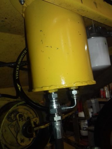
Another component required would be a hydraulic tank or reservoir. Plenty of these units seemed to be commercially available in all sorts of sizes, mostly far too big and almost all seemed rather fancy and constructed from some specialist material like stainless steel, probably for the food industry, thus making it a rather costly component. I decided that I could make a tank with a short length of 150mm diameter mild steel tube with two flat plates welded top and bottom. The bottom plate would take two fitting, one return and one supply and the top plate would need a fitting to allow filling. The lower fittings were easy, the pump had 3/8” BSP (British Standard Pipe) threaded ports so I figured that the same would be fine for the tank. The filler at the top could just be a malleable iron spigot with a screw on cap, again standard BSP kit off the shelf and still used today all over the globe (or disc for Pale Horse) and indeed beyond. I welded the bottom fittings onto the lower plate and then the steel tube and carefully filled it with paraffin to check for leaks. No leaks, so on with the top plate into which I also incorporated some lugs with drilled holes in order to bolt it to the dumper deck underside. Job done for around a tenner.
© Cardinal Puff 2023