
T.I.B Or Not To T.I.B?
PersonX: “Doc, can you just have a look at the vacuum cleaner it’s making a funny noise?”
Doc: “Err…well..err…you see I’ve got…err…an appointment with the dentist…”
PersonX: “There’s no mention of it in your 1987 Filo-Fax?”
Doc: “Err…well…err…oh just sod….”
Well, you get the idea. You ask the Doc questions like that and I’m out of there quicker than a Kojak with a vodka can clock me, QSL. Now don’t get me wrong, I like vacuum cleaners when they’re working it’s just that I hate what’s accumulated inside the dirty buggering things. Bagged cleaners are bad enough and then Dyson came along and made the situation ten times worse!
If you’ve ever had the misfortune to have to disassemble one then you’ll know that the active ingredient inside them (amongst the bio hazard) is an electric motor. If disassembling the thing was bad enough putting it back together is worse as you inevitably end up with a dreaded TIB – or Throw-‘Int-Bin. You know the, “I wonder where that plastic bit goes *scratching head*?”. We’ve all been there.
We can think of an electric motor as the reverse of an electric generator. Instead of putting electrical energy in to get rotation we put rotational work in to get electricity out. Let’s reverse engineer a small electric motor as it will help us understand how an electrostatic generator works:
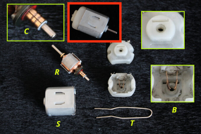
In the above image – top centre – you can see a small 3 Volt DC motor. Whoever designed these little motors must be very rich and quite possibly dead by now as I remember them from as far back as day one. As a child I was forever getting into trouble taking apart and removing the motors from toys. The thing is I wanted to know what was inside them and how they worked. Only problem was how to put them back together again – both the toys and the motor!
In the photo you can see the various bits and bobs that make up this brilliant little machine. (R) is the rotor – the bit that spins around. On it you can see the commutator (C) which has three elements, zoomed in above and (in this case) well worn. These elements connect to the three electromagnets on the rotor. This assembly sits inside the stator (S) that contains two permanent magnets – one with a north facing pole the other a south. The two brushes (B) ‘clamp’ onto the commutator elements to transfer the electricity to the electromagnets. Simple but brilliant.
The problem the Doc had as a child was re-assembling these fascinating bits so that my friend’s Big-Track would work again. The answer is ‘The Tool’ – not the Doc, the paper clip (T). If you look at the back of the motor (zoomed top right) you can see what looks like a letter box opening. This is where you insert the paper clip tool. Why? Well, it separates the two brushes so that the commutator and rotor can be seated into the back bearing. Without doing that you knacker the brushes – as I’m well aware.
At this point I was going to entertain you all by explaining the four ‘3-phase’ cycle of this humble little machine but that would be a small article in itself so I’ll do is write that up separately.
Let’s relate the above motor parts to an electrostatic machine – namely a Holtz generator (ESG):
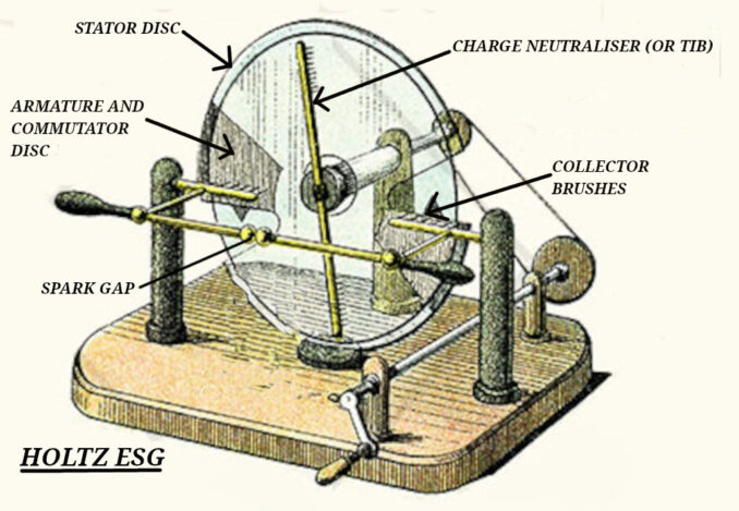
First of all let me deal with the charge neutraliser bar which I’ve marked ‘TIB’. When I was ‘reverse engineering’ this machine that bit didn’t make any sense. Why would I want to short circuit the electrostatic charge? Well it turns out you have to ‘dump’ some of the electrons to make the machine run continuously. Basically the negative collector brush can’t collect all the electrons available on each charge/discharge cycle so the armature/commutator gets saturated with electrons and the machine stops working, hence we have to get rid of them. I modified the Holtz design and made it simpler and easier to understand (I think!) as we’ll see.
The armature consists of a glass disc covered with shellac and glued onto it are two foil commutator elements. These allow the net negative charge (recall from the last article) to be ‘collected’ by the fixed brushes. We’ve got the net-negative charge on the surface of the disc but it is a poor electrical conductor so we need the metal (foil) commutator elements for the brushes to be able to retrieve the electrons.
The stator, again, is made of glass and shellac and has some funny foil arrangement on it to ‘induce’ a static charge onto the armature disc. I don’t like it, TIB. After many months (not kidding) of playing around me and Dr Peabody invented a different system – The Peabody-Finnley charge sheet (TM). So yes, you can now throw the hard-to-make Holtz stator in the bin. Not saying it’s not right, I just don’t like it – I like simple!
Constable: “Why do I have to fill this sheet in every time I arrest someone?”
Sergeant: “Cuz without it there’d be no charge!”
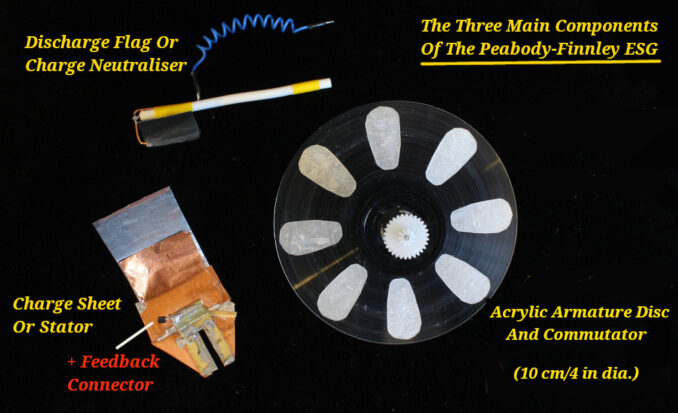
The Peabody-Finnley ESG
Created with GIMP
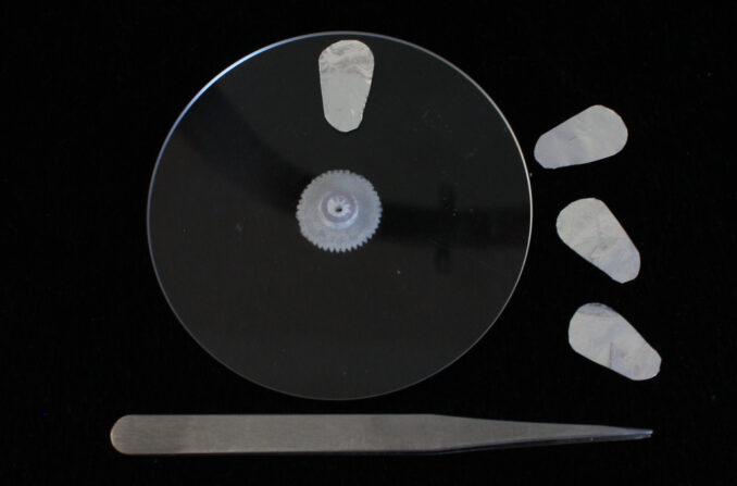
The 10 cm/4 in armature disc is made from 2 mm thick clear acrylic (Perspex) and was purchased from eBay. Two for less than a tenner and the company cut me a 10mm hole in the centre. They also sell coloured discs but I found the clear ones built up a better electrostatic charge – perhaps it’s something to do with the dye. The ‘charge sheet’ looks like a TIB but is in fact a precision engineered piece of kit. Actually it’s improvised over many months from copper and kitchen foil. It does need to be positioned accurately for optimum results hence the ‘slot’ to allow it to slide up to the armature disc. There should be very little pressure on the disc – the ‘sheet’ should just float like a disc drive head on the surface. The ‘discharge flag’ or charge neutraliser is made from a piece of coax cable, more on that later.
The following is how I made the armature disc ‘s commutator elements. I found that eight was about right for a 4 in disc:
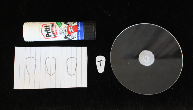
First I had to find a glue to attach each of the commutator elements to the disc. PVA came to mind but it’s too runny. I could use a contact adhesive but that would damage the acrylic and be very messy with no easy way to clean the disc. The solution came with good old Pritt-Stick. Water based so easy to clean and it allows for some positioning of the elements while it drys. It’s surprisingly good at sticking the foil onto the acrylic and will take warm water washing after it sets. This is good as the disc needs to be grease free for it to work.
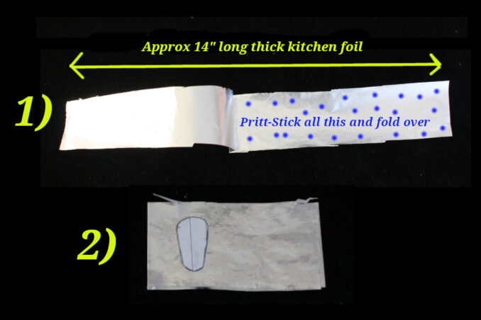
To make each of the elements take a 12-14″ strip of thick kitchen foil and fold it in half gluing each half together – see image above. Do the same again so that you now have four layers of foil glued together. Stick the paper element templates onto the foil with Pritt-Stick. Leave to dry (about an hour) and then cut them out. You’ll now have four elements all stuck together. Simply drop them into boiling water to separate them. Now carefully stick them onto the disc using (you’ve guessed it!) Pritt-Stick! Allow to dry for 24 hours. Wash your finished armature disc with cold or warm water and soap.
Here is a photo of my ESG machine (above bits all in place) running and producing a 30kV spark which is about the maximum the 4 inch disc will produce. Okay, it looks like a roadside IED but it did end up nearly TIB’ed on several occasions! The disc rotates at a speed of about 500 to 1500 RPM and any faster it just stops working. A 10mm spark is produced about every 4 to 6 seconds by charging two 20kV 1nF capacitors in series – more about capacitors in part 4.
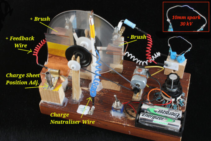
Note the (essential) positive feedback wire and the ‘earth’ point for the charge neutraliser, which is just a self tapping screw driven into the wooden base. Wood is a fairly good conductor at these voltages!
Also note how the ‘charge sheet’ sits in the machine and that it is adjustable. It has to be set up fairly accurately to get optimum results.
In the next part I’ll explain, in a little more detail, the machine’s ‘charge cycle’ and how it relates to the positioning of the brushes, neutraliser and charge sheet.
© text & images Doc Mike Finnley 2025