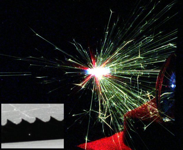
Melting a hole through steel: The above image needs a little explanation!
The Doc messed up his camera settings and under exposed the image. So I loaded it into Gimp and played with the curves and brightness and ended up with this artistic result. I like the noise and colours. It reminds me of the front cover of a 1970’s text book on lasers.
The laser was focused onto a ‘coping saw’ steel blade. The inset photo shows the tiny hole that has been created by the beam.
These blades are about 0.3 mm thick and the distance between the teeth approximately 2 mm. We can safely estimate the diameter of the hole to be about one twentieth of a millimetre.
Note the ruby laser ‘speckle pattern’ on the focusing lens’s edge and the blue highlight from the flash tube on the right side of the image.
If you look carefully at the centre of the ‘saturated-to-white’ main image you can just make out the ‘saw-tooth’ pattern of the blade’s teeth.
Alignment, alignment, alignment and alignment
I bet that you are as fed up of reading that noun as I am of writing it.
Well let’s crack on and put this project to rest.
I’m not ‘in-lining’ this image and so I will just provide a link to it: https://imgbox.com/lWyRVWcZ
It simply shows the general alignment set-up. The distance between the ‘screen’ and the ruby laser’s OC would be at least six to eight inches to allow for the OC mirror adjustment. The distance between the aligning laser and screen is less than an inch.
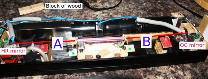
In the above (messy) image we have the all important ‘block-of-wood’, which you may recall from part 3, henceforth to be called the BoW. The flash tube has been removed.
The red line represents the path of the aligning laser beam. It passes through the screen then the OC mirror mount (note that the OC mirror is not in place). It then passes through point B, the ruby rod, point A and finally strikes the HR mirror.
The object is to make it return along the same path, exactly.
Step 1 – Align the ruby rod
I covered this in part 4. We’re doing the same thing while the ruby is inside the laser. The green dots in the above photo highlight the small pieces of cardboard that lift/lower either end of the ruby rod’s mount.
Insert the BoW at point A. This blocks the alignment laser light from striking the HR mirror. We only want the light from the ruby rod.
Adjust the small cardboard ‘wedges’ until the reflected light shines back through the little hole in the screen. You should see some interference patterns on the screen. See the next step for a GIF link.
Remember: the OC mirror is NOT in place at the moment.
Step 2 – Align the HR mirror
Remove the BoW from point A so that the laser now strikes the HR mirror.
Adjust the screws on the HR mount until the light passes straight back through the ruby rod and the little hole in the screen. You should see an interference effect like this GIF (note the He-Ne OC mirror reflection): https://imgbox.com/YmSUHAPV
Step 3 – Align the OC mirror
Insert the BoW at point B. Carefully install the OC mirror. Note that neither the aligning laser nor the laser being aligned should be moved throughout this process.
Adjust the OC mount to get the light shining back through the little hole.
Remove the BoW from point B. If everything has lined up you should get a lot of destructive interference. What I call the ‘faulty florescent tube effect’ can be seen in the ruby rod: https://imgbox.com/o73B3ytb
If you see a ‘splodge’ or distortion on the screen it means that one (or more) of your components is misaligned. You can always try a quick fix just to see if your laser works. In fact I often use this final step anyhow!
Step 4 – Cheat a little
With no BoW inserted (and the OC installed) re-adjust the HR mirror. If you are lucky the beam should align pretty well. If you can’t get the laser light back through the screen’s little hole then I’m afraid you’ll have to start back at stage 1.
Even so it might be worth firing the laser to just see what happens!
Conclusion
The 1960s started with a device that was described (jokingly) by Irnee D’Haenens as “a solution looking for a problem”. You might recall from part one that he was the physicist working with Theodore Maiman when they ‘fired’ the first ruby laser in May of 1960.
By the end of the decade men had walked on the Moon and taken with them retro-reflectors. An array of ‘cat’s eyes’ reflectors.
Bouncing a ruby laser’s light off of those mirrors allows us to measure the distance between the Earth and the Moon to within centimetres.
As a physicist remarked: “It’s the equivalent to measuring the distance between New York and Los Angeles to within 0.25 millimetre accuracy”.
Without Maiman’s ruby laser this would have been impossible.
© text & images Dr Mike Finnley 2018
Audio file