
Project 1: Scope Dials
Welcome all and please gather round so I can waste a few minutes of your precious time on describing something that didn’t really need doing and no doubt would interest few.
I’ll begin.
A few months ago, on a whim, I purchased a crossbow. Why? Because it was cool! Regardless of the reason, once it arrived it was assembled within about 15 minutes and the first bolts were flying. Ignoring for the moment the herculean effort required to first string the thing then drawing it each time, it was fun to just shoot off a few. Now, it did come with a reflex scope which, on that first day, I did attempt to dial in and get centred so it was shooting accurately at around 20 yards. My attempts were less than successful however. After shooting until my fingers couldn’t face drawing the bow again it was still pretty inaccurate. I put it away dejectedly and swore to sort it the next day. Fast forward to the next day. Just to see how straight the bow was actually shooting I removed the scope and shot a few bolts using the iron sights. To my great delight I was shooting far more accurately at the same distance than I did with the scope. It didn’t go back on.
In the following months I shot it a few more times just to keep in practice and was pleased with my progression, I was getting more accurate every time. In the intervening time I had ordered a new scope for the air rifle. When it arrived it came with a free rail mounted laser dot. Since the rifle is more for long range target shooting it was useless for that. So I thought, “why not try it on the crossbow, it’ll make for faster aiming.” And so I did. The results were acceptable given that it hadn’t been dialled in. Unfortunately doing that required the use of an Allen key which, while not a great inconvenience, was annoying. And so an idea formed. I could do something about this. (Bear in mind, once it had been dialled in to the range I needed it wouldn’t be changed again, it’s not like I was going to start competition shooting or anything. But damn it, I wanted the option!)
All I needed were a couple of simple dials that could be fixed into the Allen bolts on the scope.
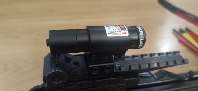
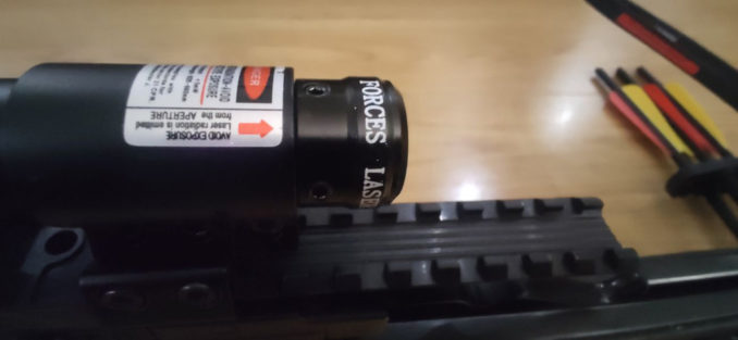
As can be seen from the next picture, the bolts are located about where you’d expect them to be.
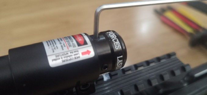
The next thing to do was to find out exactly what size Allen key was required to adjust them so I broke out the half decent set rather than the general use, just so it would be a little more accurate.
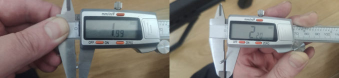
Once that was sorted, rather than assuming that it is what it says it is, I measured the Allen key itself in 2 places, on the flat to flat surfaces and on the ‘point’ to ‘point’ (as they don’t actually go to a point, they’re rounded).
The only other piece of information I’d need was the depth of the recess in the Allen bolt. This was approximately 6mm but I’d also need to account for getting past the shoulder of the main body of the scope which was an additional 2mm. Given another millimetre just for clearance meant that the ‘shaft’ of the dial would need to be 9mm long. Given that I was going to manufacture these using a 3D printer, some precision (not EXACTLY a lie) design work would be required. Time to break out the CAD!
Now this should be easy, right, it’s an Allen bolt, essentially it’s a hexagon with rounded off corners. Turns out it was pretty easy. Firstly the initial hexagon shape was drawn followed by marking out the extent the ‘points’ should reach.
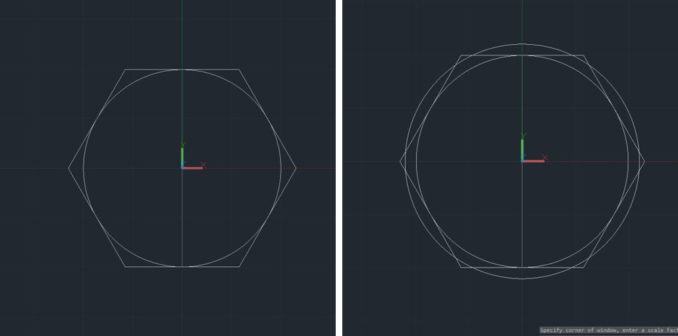
Luckily CAD has a facility for rounding off corners called ‘Fillet’. I know the amount I need to reduce the ‘points’ by but unfortunately the Fillet tool doesn’t work like that, you input a radius for the curve with the centre being located at a point equidistant from the two lines you’re filleting. I’m sure there’s some arcane and complicated formula to calculate the required radius for a specified reduction given the relative angles of the two lines to be filleted. Instead I used the old, trusted trial and error method to get it as close as possible (it’s within 1/100th of a millimetre) which took less time than it would have taken for me to investigate whether a formula does in fact exist.

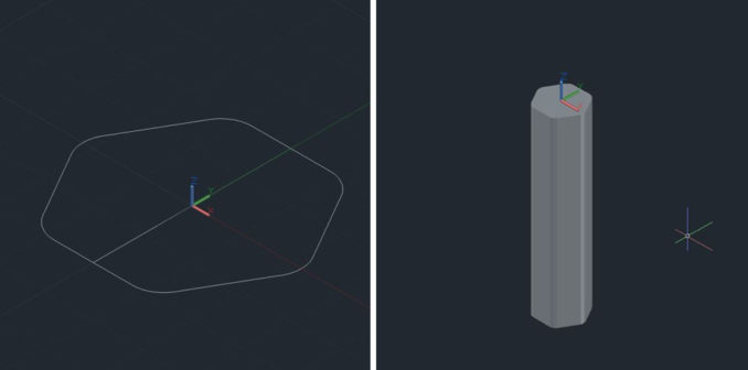
As can be seen above, this shape was then simply extruded to the 9mm height required (extruded downwards so the top face is accessible in this view and reduces the amount of changing views required when constructing the top section).
The next step was to create the top dial that would be used to turn the little ‘Allen key’. I had decided that this would need to sit within the profile of the scope body to be protected from the majority of knocks while being transported. It would have been simple to create a round dial to just stick on top but I wanted to add a little texture just to fingers didn’t slip when turning the dial.
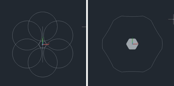
A dial diameter of 11mm was selected. I then randomly drew a circle with varying radii until it looked about right and used that to cut out 6 ‘notches’ in the circle (in keeping with the hexagonal shape of the shaft). Once this looked about right this was again extruded to the required height of the dial (I chose 8mm, not big enough to be too obtrusive but not so thin that it became flimsy).
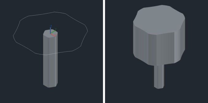
With that done, all that was left to do was to join the two pieces together to form one solid object. This was then exported as an STL file to enable it to be loaded into the program for the 3D printer to adjust the required settings.
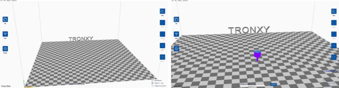

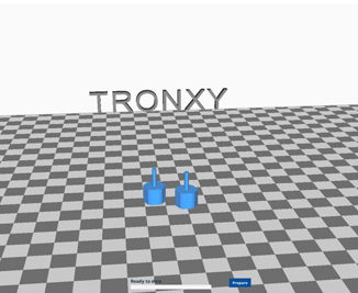
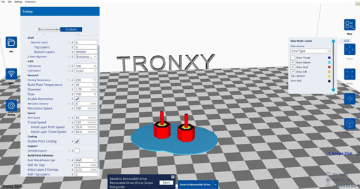
As can be seen from the images above, the model is imported into the slicing software (in this case the software that came with the printer) and various adjustments can be made, rotating so that the main bulk of the object is the part laying against the bed then creating a copy of the model (as 2 are required) which is automatically placed to provide adequate spacing. The interface, once used to it, is very easy to use and this took probably 30 seconds to achieve.
Next comes the task of deciding how the printer will actually produce the model.
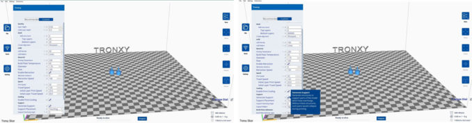
The settings are numerous and, while you can do a search online to find out what they should be, nothing beats experience. No two printers behave the same (even the same models) so it will take some messed up models before fine tuning these. I’ll just go through a few of the main settings here to give an idea of what to be aware of:
Layer Height – Essentially this is the diameter of the extruded PLA filament (which in its original state has a diameter of 1.75mm). The lower the number, the smoother the finished model (in this case it’s set to 0.04mm, the finest setting). This setting will determine how many total layers (or ‘slices’) the model will need.
Initial Layer Height – The height of the first layer as expected. The reason this can be configured separately is to improve adhesion to the heated plate it’s extruded on to. If the layer height is too small then as the extruded PLA is ‘dragged’ along the plate it will pull away.
Wall Line Count – How many lines of thickness the outer walls of the model will contain (each wall line equal to the thickness of the layer height). This creates a solid outer wall whose thickness can be specified. The reason for this specificity will be explained later.
Top/Bottom Layers – The same as the wall line count but for the top and bottom surfaces.
Infill Density & pattern – The infill is the percentage of the space between the walls/top/bottom that will be filled with material. 100% will create a fully solid model. 50% will fill half of the area with material which obviously creates a less solid structure but saves both time and PLA when printing. The pattern determines how the material is printed (e.g. lines, zig-zag ). 100% infill will only generally be used for objects that will have some form of physical stress at some point. Varying degrees of lowering infill density will be used for more decorative objects depending on complexity and size.
Material – Specifying the temperature at which the nozzle of the extruder will operate. Again, this is more a matter of experience but online guides are quite accurate. Also the temperature of the heated bed (on to which the material is extruded) can be set to the users preference. This will determine how the first layers adhere and how easily the model can be removed once it’s completed.
Support – While not an issue on this model it is one of the most important settings. This will determine where the printer will build support structures to hold up any overhanging aspects while being printed (it really doesn’t work printing straight to mid-air). The method for the program selecting where to automatically place supports is by selecting the overhang angle between 0° and 90°. At 0, no supports will be inserted. At 90 supports will be inserted wherever there is an overhang, no matter how slight. While supports are essential for creating models they do of course increase both the print time and material used. Also, where they make contact woth the model will leave artefacts when they’re snapped off requiring additional sanding and finishing.
Build Plate Adhesion – This will create a primary structure beneath the actual model to improve adhesion to the plate. There are a few types (brim, raft) and the amouth they extend past the model can be specified. The structure is generally 3 or 4 layers thick and has an infill density of around 50% with no external walls or top/bottom. This creates a flexible sheet that is easier to remove from the plate upon completion and also from the model (though again this can leave artefacts that will need sanding)
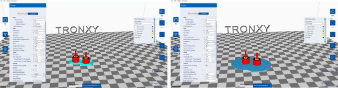
Once all of these setting have been selected the software then ‘slices’ the model into the layers that will be printed. The last 3 images above show the model after slicing (note the build plate adhesion below the models). The model can be viewed as before but a slider can be moved up and down to see how the model will be printing at each layer (helpfully colour coded). It will also give you an estimate of how long the model will take to print (though in my experience it will take about twice as long) and how much material it will take to create the object. Once the settings are acceptable the model is saved to a micro SD card in for transfer to the printer.
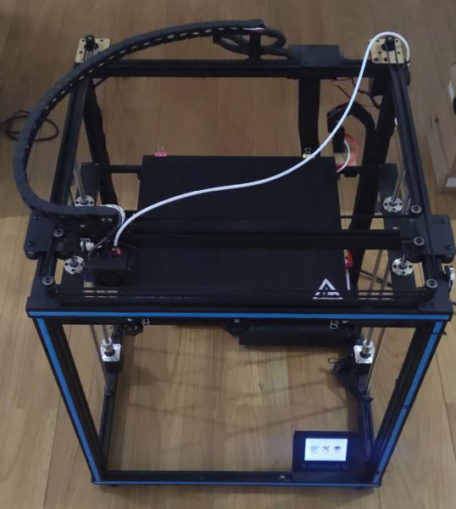
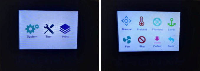
The printer I’m using is the Tronxy X5SA. It has a printable area of 330 x 330 x 400mm which, while not immense, is a fairly large print bed for a printer in its price range. Far from doing an indepth review myself (plenty are available online) I’ll just say that I’ve had this for around 18 months or so and it’s served me well. Admittedly I don’t do a massive amount of printing (mostly prototyping for people or items for work) but it’s been easy to use and very reliable. The first menu upon powering up provides 3 options. System takes you to the system information and settings, Tool takes you to…well….tools for setting up the printer (which I’ll go into presently) and Print where the model to be printed is selected from the SD card and started (alternatively the printer can be connected directly to a P.C.).
Before starting the print there are a few things that need to be done to ensure the best print possible. Going into the tools menu provides these (image 3 above). I’ll go through the sequence I use to set up.
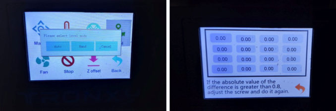
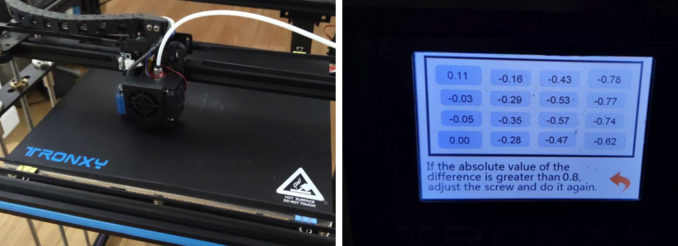
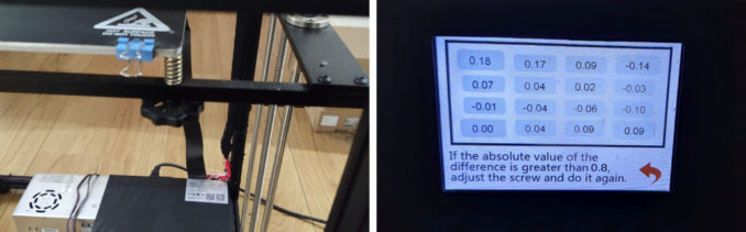
Levelling the bed – The first thing I do is to level the bed. The printer has an Auto function (which doesn’t level the bed for you) which brings the bed to the extruder at 16 positions. The first position is used as a reference point and the rest are how far the bed is from that reference point (in mm). As can be seen from image 4, it was pretty far off. The text below the measurements states that min-max should be no more than 0.8mm. I prefer to work to 0.2mm. The screw it mentions is shown in image 5. There are 6 in total (3 front and 3 back) which adjust the elevation of the bed providing quite accurate positioning. As can be seen from the final image, after adjustment the bed was much flatter. Now, after my previous statement that I prefer to work to 0.2mm this may not seem acceptable. For this model however I know that it will fit within the area encompassed by the 4 measurements in the middle, so I’m only interested in those ones.
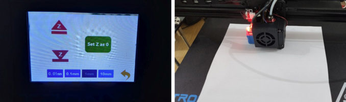
Z Offset – Next is the Z offset. This specifies how close the bed is to the extrusion nozzle at ‘standard’ position. If the nozzle is too close then the extruded material will be compressed and spread, not to mention the possibility of it sticking to the extruder as it can’t escape quick enough. If the nozzle is too far away then the material will cool too much before hitting the bed and will not adhere. So how far away does it need to be? Well a simple way to determine the correct distance is to insert a sheet of paper between the two (I have a sheet of standard 80gsm paper that I always use) and adjust the bed upwards ( by increments of 10, 1 0.1 or 0.01mm) until the paper can be pulled from between the bed and nozzle with some resistance. Again, this is a matter of experience but it doesn’t need to be micrometrically perfect.
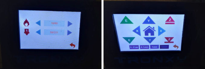
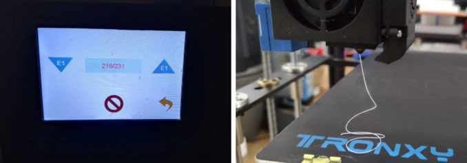
Filament preparation – The final stage is to ensure the extrusion nozzle and filament feeders are working correctly. The first thing to do is to preheat the extruder and the heated bed (generally to a slightly higher temperature than you’ll be using for the print to allow for a little cooling time). The bed will then need to be moved away from the nozzle a suitanle distance using the manual controls (image 2). The filament can then be fed into the extruder to ensure it’s flowing properly. It can be manually started to automatically feed in or out of the extruder or to stop completely (image 3). Image 4 shows the material being extruded from the nozzle (this print is using black PLA but to begin with the nozzle extrudes material already in there, in this case the last print I did was with white so the extruder was left to run until the black started flowing. Once this has been achieved the filament is stopped and the pre-heat is switched off. Time to actually print.
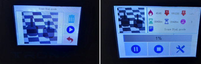
Going back to the main menu, the print option is finally selected! This presents you with a list of the files available on the SD card. The model is selected and you are presented with an image of the model to be printed (sometime solid, sometimes transparent, don’t ask). From there it’s just a matter of pressing the print button and you’re off. As soon as the nozzle and bed are up to the temperatures specified the print begins. Image 2 shows the progress screen shown during printing. This displays overall progress (of course), temperatures of nozzle/bed, time elapsed, estimated time remaining and nozzle speed. At this point it’s just a matter of sitting back and trying not to watch something appear out of nothing (it is strangely hypnotic to watch). It should be said that during printing the only thing that can be heard is the fans of the power supply and the nozzle. During this print the machine was sat beside me in the living room and I was watching a movie without having to turn up the sound. For what it is it’s very quiet.
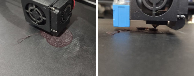
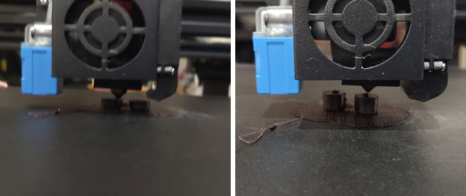
These images show the print in progressing states. Image 1 shows the raft being printed below the model. The next two are just the ongoing build of the model. In the final image though a problem can be seen. The nozzle no longer appears to be in contact with the model and is not extruding material. At that point continuing to print is pointless and so is cancelled.
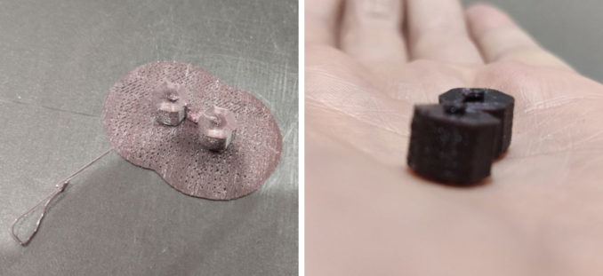
As can be seen from the last two images, the actual part of the print that was necessary is the part that didn’t print. Figures huh? The reason for this? I don’t know for certain (I’ve printed models with parts much finer than this with no problems in the past) but I suspect it’s to do with the material I was using. Because it was only a small print I used a part-coil of PLA that I had lying around. When storing filament it should be kept in as moisture free an environment as possible, where possible in a vacuum sealed bag. This one wasn’t. Once moisture gets into the material it tends to become brittle. My guess is that it snapped off somewhere close to the extruder which created a large enough gap to prevent any further material being in contact with the model. At that point it’s game over.
Now, after all that, normally my hard-headedness would kick in and I’d just keep doing it until it was right. In this case however my determination is somewhat tempered by the fact that I was creating something I didn’t really need in the first place. Just out of curiosity I may try it again in the future but at this point in time I’m quite happy with forgetting the whole thing and starting to search for something else that doesn’t really need doing. Until next time…
© Standard Issue Male 2022
