The run up to Christmas involved a few days helping out at Tanfield Railway – long hours and endless sanitising Santa’s Grotto meant not a great deal of work was done on the layout.
Once Christmas day was all done and dusted, with minimal family upset, then there was the opportunity to consider next steps.
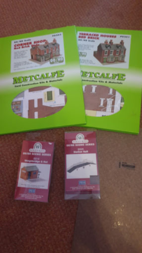
I had received the hinted for card and plastic kits and had plenty of other things to be working on.
© Sweaty Dave, Going Postal 2020
Rather than make a start on the kits – they are best done when chained to the desk ‘working from home’ – I thought I’d have a look at a couple of other elements:
© Sweaty Dave, Going Postal 2020
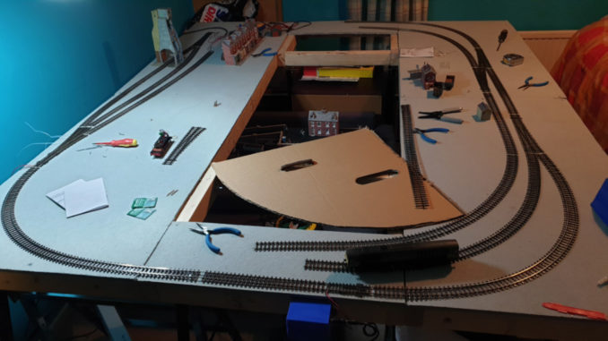
Baseboard & track
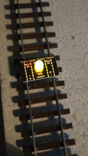
The track tester arrived – a small piece of electronic gimmickry that tells you when the track has a decent power supply and if it is AC or DC (orange is good). It showed that until I signed into the controller, no power was sent (ok, quite flash), and different points behaved differently – some allowing power to all branches, others only to the direction set – as electrofrog points they’re meant to power all routes – hmmm. The former is best for DCC, the latter for DC.
© Sweaty Dave, Going Postal 2020
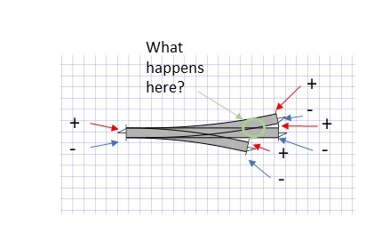
The three way point in particular needs some development. Reading the tiny print on the packaging, it ‘recommends’ two point motors, linked to power switches that will bring the various tracks to life. Fair enough really – when you have two paths that can be chosen, the point where it crosses can give an electrical short if not wired correctly – say as an example you were going left on a DC layout. The left hand rail would be -ve, the right hand one +ve. If you were going right again the rails have to be -ve and +ve respectively.
© Sweaty Dave, Going Postal 2020
The problem being that middle piece of metal serves both options – firstly as right rail but then as left – so needs to switch polarity depending upon which route is taken.
Naturally it can’t be both or you have an electrical short. That does energise both sides with that particular polarity so insulating joiners have to isolate it from the next section – not an issue on the track in use, as they are correct, but to safeguard the other line and stop a short. Basically until I purchase a couple of point motors, the switches triggered by those motors and the control module to run it all, that section is put to one side.
In the meantime I have ordered the point motors needed above – as usual this year most are not easily available as the hobby has taken off with lockdown. They are the long type that can be fixed under the baseboard. I’ll also need a controller to run them – rather than wires from a central point as in the cyclists layout – DCC layouts only need a feed from the track to a small controller that can run say four accessories, so one of those ordered from train-tech (http://www.train-tech.com/index.php/points-control)
With two point solenoids for the three way and likely at least one other point and a signal on that baseboard, I ordered a 4 way controller.
Scenery
Following kind comments about the last article, I decided to have a think about the scenery and topography. The vague plan is to have the coalmine pretty much on a level section, but a slight raise in the land behind it, where the double track mainline climbs a little before crossing a valley and descending on the other side.
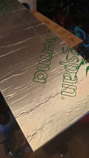
The scenery is made up of a few different elements, Firstly a few sheets of Kingspan foam to make the base, plus some modelling plaster bandage (mod-roc) and paints.
© Sweaty Dave, Going Postal 2020
The Kingspan needs to be cut and sculpted to give the broad outline of the change in height planned. In this case both sides will rise slightly, the track in something of a cutting to minimise the height climbed in the space available, before placing a viaduct at the top of the layout where we have an open baseboard – that gives me the space to drop the level below that of the rest to give room for a valley and stream/river.
I made a start cutting the foam – it doesn’t half make a mess – no special tools, just a kitchen knife and it works quite well. It is easy to saw into the right size, then it is a case of picking off the foil and paper skin then shaping it to something a little more natural. It doesn’t have to be perfect, as the next step is to fill any problem areas with polyfilla before soaking and draping strips of the plaster impregnated sheet and smoothing that out to the final shape.
As ever, I began with a bit of a prototype to see how it went – is it too fragile and likely to snap? Is it just plain rubbish? Initially the plan was for the track to climb the full height of the foam – around 3 inches, but in such as short run that is impractical, so I’ll bring it down in height to say half the foam height and have it in a cutting before crossing the viaduct and down an equivalent piece on the other side. The stuff gets everywhere, it’s like having a fight with a burst beanbag – foam everywhere. The jump from baseboard onto the foam is too great, it is then recklessly steep.

© Sweaty Dave, Going Postal 2020
I’ll go for the more expensive route and buy some pre-made foam risers (about £20) to give the correct gradient and use this foam around it as the surrounding hills. They raise the track up at 4%, taking 2 feet to raise 1 inch – it’ll be one per track to go up and one for down the other side.
Wiring
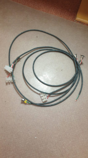
Ages ago I had talked about having each of the baseboards independently run so they could be disconnected and stored away or moved easily. I’d not done a lot of that work to create the wiring needed (soldering those 5 pin din plug sockets) – the holidays was an ideal time to do so.
© Sweaty Dave, Going Postal 2020
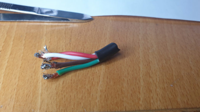
A few ham-fisted attempts and I found the most successful way to make the wires was to strip the wires slightly more than needed, thinning a few strands of copper out. This was necessary, as the 12v automotive wire was too thick for the sockets. Once stripped, the ends are given a coat of solder, the same on the socket points then bring the two together. Where it is really rather messy, add some insulating tape to prevent adjacent wires touching. I wired up four of the sockets before being distracted.
© Sweaty Dave, Going Postal 2020
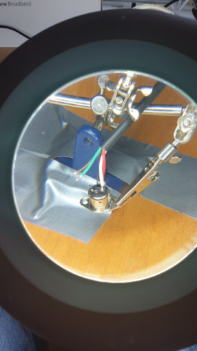
Fitting them to the baseboards is easy enough, though the traditional wiring blocks that are mounted under the board to join it all up are really for larger gauge wires – meaning poor connections. Even trimming the inner two wires slightly shorter to allow the outer ones to reach the block has minimal success.
© Sweaty Dave, Going Postal 2020
I might have to follow up on Sozz’s suggestion of a newer variant for easier connections. Anyhow three of the boards now have their sockets and wiring block, only another three to go… I’ll then have to connect each together, to the controller and to the track upon each section to get the wiring completed.
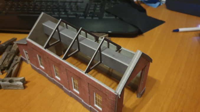
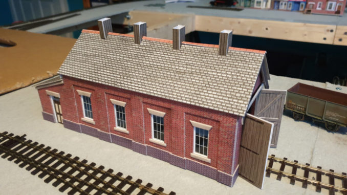
Remember my complementing Metcalfe card buildings? (no sponsorship sadly). Well they surpassed themselves with the single engine shed. It includes a beautifully engineered set of roof trusses and smoke hood that sets up the interior despite being unlikely to ever be seen. The trusses fit into pre-cut grooves in the walls and are millimetre perfect.
© Sweaty Dave, Going Postal 2020
I have somewhere a flashing light that mimics a welder’s torch – when the final site for the shed is in place, I’ll include that light as if work is going on inside.
© Sweaty Dave, Going Postal 2020
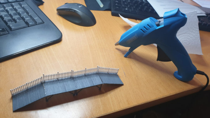
Finally, upon the first day back at ‘work’, with nothing going on, no meetings organised and the boss still in St. Lucia, I tried building one of the plastic kits. The contact adhesive I’ve been using is years old and probably well past being useful, so tried digging out a hot glue gun.
© Sweaty Dave, Going Postal 2020
That was equally unsuccessful, the glue setting as soon as it emerged from the gun, leading to the effect of a kit made by an energetic eight year old with the shakes. Next step – I’ve ordered a decent contact adhesive and precision dispenser to hopefully improve upon the mess.
© Sweaty Dave 2021
The Goodnight Vienna Audio file