© Sweaty Dave, Going Postal 2020
With three baseboards built and fitted together and a fourth ready to go, we have a stable base for the layout. Yes, another two boards will be added later to give a full loop but there is plenty to be getting on with for now. Besides I’d have to find a bigger room as three are filling all the space available.
© Sweaty Dave, Going Postal 2020
The strands mentioned last time are still all running along
Baseboard
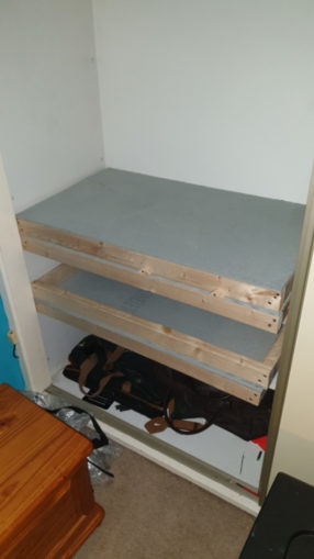
The boards are fitted and bolted together and the cupboard is filling up! Since this pic was taken I have added extra levels so each board has a foot or so clearance above it for scenery and track. I have drilled holes for the 5pin din plugs, each of those has 4 core wire soldered to four of the 4 pins – 2 for AC, 2 for DC leading to a junction block and then on to the next din for passing to the next section. The wiring is a little over sized – the standard wires you get from the Automotive sector, meaning soldering tiny 5 pin plugs is a bit fiddly. It’s a job low on the priority list I must admit.
© Sweaty Dave, Going Postal 2020
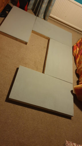
Once the track is laid out, the baseboards will be painted and scenery added when features are built. The boards weren’t quite flush – finding a flat surface big enough to line them up is not possible, but a bit of post-creation fettling has brought them into line. So far those triangle chocks don’t seem too important when the bolts are so heavy duty.
Track
I received the PECO catalogue, which shows that track has advanced a great deal in recent years. I was going to repeat what I’d done with the last layout, namely buy standard settrack pieces and make it all up, but having looked at the other options, really should go for a better standard.
What is he on about you may say?
Track comes in a number of standards. For OO all the manufacturers build fixed track pieces to the same geometry, size and shape – so it is interchangeable. Points turn by 22.5 degrees, a 2nd radius turn has a radius of 17 1/4in, and so on. They are known as ‘Code 100’ track. This is a standard that runs all trains of that gauge, including older ones that are more toy-like and have deeper wheels (flange depth up to 1.6mm #filth). The rails are slightly deeper/higher than would be if true to scale, to stop older trains from derailing all the time.
© Sweaty Dave, Going Postal 2020
The next step up is moving to track that is to scale – i.e. where the depth of track matches that of real life 4mm to 1ft. This is known as ‘Finescale’ or ‘Code 75’ and gives shallower track and sleepers. It is a bit more fragile and the angles and curves of points are less sharp – generally only 12 degrees, meaning more space is taken up for a junction. This track also does not generally come in standard fixed pieces other than for junctions, but you have to make it up from long runs of flexible track – it can be straight or curved.
As the track is less deep, the flange depth on wheels (not filth but the depth of the bit that sits inside the rail) is only up to 1.143mm, rather more shallow than code 100. One other element is that the points tend to no longer be isolating – great for DCC in some ways, but adding complexity in others as short circuits can occur upon loops of track.
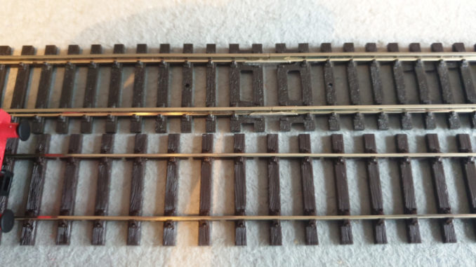
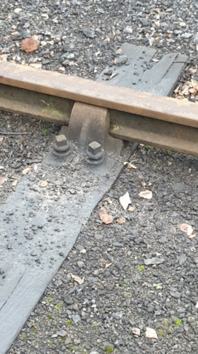
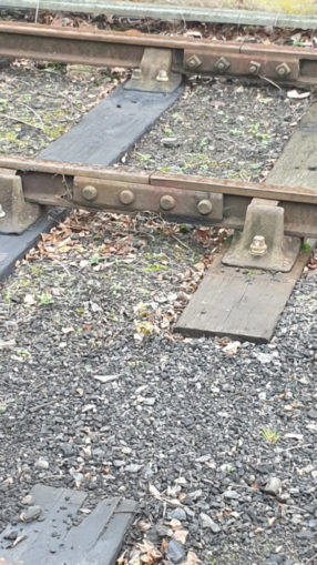
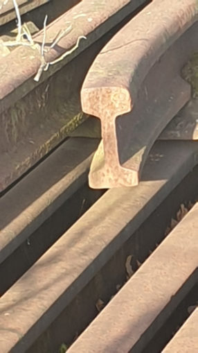
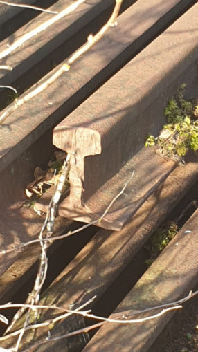
Finally there is a new range called Bullhead Code 75. The same depth as finescale – (hence the 75). For this type the rail is the same shape as that on most railways lines up until the 1960s when concrete sleepers and flat bottomed rails came in. The sleepers are scale thickness and the chairs holding the rails include details of 3 bolts holding them in with a flange depth of 1.15mm. In addition the joiners between rails look like the real thing with four tiny bolts visible. There are very few points or crossings made of this so far, but it is available in flexitrack. I aim to use bullhead track where possible and finescale for junctions.
© Sweaty Dave, Going Postal 2020
© Sweaty Dave, Going Postal 2020
© Sweaty Dave, Going Postal 2020
© Sweaty Dave, Going Postal 2020
Flexitrack is something I was going to have to move to – rather than use the fixed radius of the set track, this can be bent and shaped into any form of curve, within reason. Once set in that shape the rails have to be cut to line up, so in effect the track is really just used once and cannot be reused. To achieve gentle curves a semi-flexible ruler is used, similar to one of those lead rulers Old Trout would recognise from maths when drawing graphs.
This does mean the track plan so carefully constructed is now no longer viable – the shallower junctions meaning the complexity built in is no longer possible, something I do see as a big drawback and one that mean the decision to switch is not taken lightly.
I rang the local model shop – the bloke is just about hanging in there and needs some business (www.jandjmodels.co.uk). He didn’t stock that type but was happy to order it specially. He did note that lockdown has meant a huge demand for model items – Peco being bombarded with orders, so it could be up to three weeks to arrive. He priced up my requested list of track. Once I’d got over the price gave the go ahead and he ordered it.
Power and Control
As mentioned last time, DCC is the way I’m going to run this thing – again, it’s something I’ve not done before, so a new challenge. Most controllers are prohibitively expensive, I did consider a secondhand entry level one called PCC Power Cab which you can get for about £130 on ebay, but in the end plumped for a microprocessor one, also on ebay made by a bloke in Fife.
Bill Cuthbert sells a small number of these on ebay for £50, you have to find your own power supply (an old laptop one providing 15v DC is needed) and also has a couple of apps on the app-store – a free one and an £8 more advanced one, to control it all – say £70 all in.
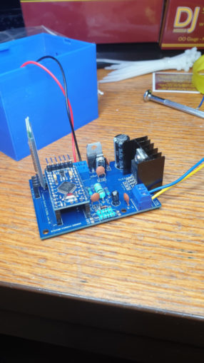
© Sweaty Dave, Going Postal 2020
You have to make absolutely sure the power going in is the right way around and 15v. The device has a Bluetooth connector to talk to the phone and a couple of wires to the track giving 16v AC along which it then sends signals to control engines and accessories. As the connection to control is bluetooth, this box can be hidden away under the board when operational.
Despite a hoard of cables and transformers I did not have one that provided 15v – one claimed to do so, but was running at 18v – which could be expensively high.
The controller turns up as a kit – the Bluetooth dongle plugs in easily enough and there is a 3d printed blue plastic box to house it. You also get a socket for the power supply but need to solder wires to the socket and then connect them onto the board. Similarly run a couple of wires from the output through the box and connect them to the track. I bought a laptop power supply running at 15v (most run at 19v these days) and soldered some wires to the socket. Upon connecting it all up, a couple of lights signified life then BANG! as the rectifier on the board failed spectacularly – it was like one of those youtube videos of the bloke that keeps electrocuting himself.
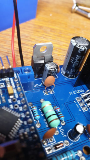
© Sweaty Dave, Going Postal 2020
I dropped Bill a note with explanation and pics – he agreed the component had failed and promised to send a replacement out next post, with this one to go back.
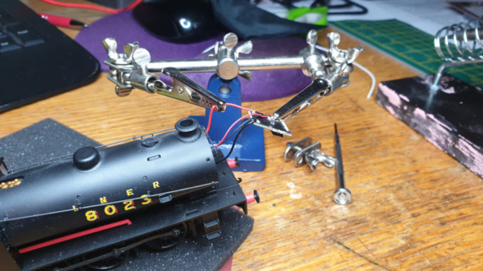
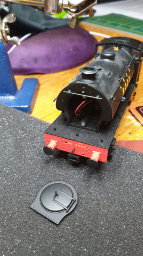
While waiting there is one other element needed – when the controller is working, each item it is talking to needs a small chip that can understand the signals and convert them into activity – this could be changing a point or signal, or most importantly, moving an engine. I bought a £7 chip from mawson-models, another ebay seller who has not been going very long. He had a Gaugemaster loco decoder with the right number of pins (there are various ones available so choose carefully). The front of the engine is held on by a couple of small magnets, so easily slides off to reveal the DCC plug. To run on an old 12dc normal layout, there is a ‘blanking chip’ in place, this is swapped for a DCC chip to convert it. Where you see engines advertised as ‘DCC compliant’ that means they have this socket in place. Many older engines do not and converting them requires a bit of rewiring, not advisable if you can avoid it.
© Sweaty Dave, Going Postal 2020
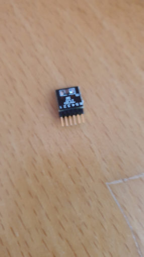
As you can see the wires are very thin, and the chip a bit of a squeeze. Note to self, do not try to ease it out by pulling on the wires – one snapped so I was left with the prospect of a £150 loco being worthless.. Some emergency soldering and all was back again. No sign of any damage or short circuits
© Sweaty Dave, Going Postal 2020
A couple of days later the new controller arrived as promised, so very carefully it was wired up again, checking and re-checking the polarity of the power supply. Once again it came to life, this time no explosions! I found the Bluetooth signal and connected it to my phone, all good. I set up a quick test track from some spare bits from the last layout and added the now chipped engine.
Two steps forward… well it sat and buzzed at me, refusing to move or respond to commands. I researched CV codes (they set the speed, acceleration and braking characteristics), debugging options and even bought the more expensive app. By now, having had one explode, the engine wires break and now not work I was near ready to chuck it in the bin and left it for the night.
A couple of days later and, in a better mood, I had another go. Having found a few websites talking about CV values (all very vague, nothing specific to this particular engine) What I did notice was the chip was very similar to the blanking chip already in there – in fact identical. At first I just assumed that was what they looked like, but eventually did google to see there should have been more components – they’d sold me a blanking chip! Trying to read the CV values confirmed it – it simply came back with an error message. The engine was buzzing as the blank chip was feeding 16v AC directly into the motor – hopefully not breaking it…
© Sweaty Dave, Going Postal 2020
One refund secured from the apologetic supplier and now I’m waiting for another one to arrive, this time hopefully the proper match for the engine. Who said this stuff is easy?
© Sweaty Dave 2020
The Goodnight Vienna Audio file