After moving home in June this year, the new place needed a fair bit of attention outside, re-pointing brickwork, replacing wood decking and rebuilding a badly blown wall sitting on a rusted steel lintel were just a few of the things that had kept me busy. The two year old British Gas heating system was still under warranty and in the last months had supplied hot water without fail and so there really hadn’t been any reason to spend time looking it over… or so I thought, until last week when with a bit of a chill in the air at both ends of the day we switched on the heating. The following morning we had plenty of hot water but stone cold radiators.
The full system consists of a boiler, water tank and a Honeywell timer (model ST9400C) screwed to the wall (and seemingly at the most inconvenient height possible). The interconnection wiring is managed inside a 10 way junction box. The pipe work has a pair of 2 port electrically operated motorised valves to control flow. In order to explore the problem, the first step was to remove the lid of the junction box to make sense of the electrics…

© Verax Cincinnatus, Going Postal 2019
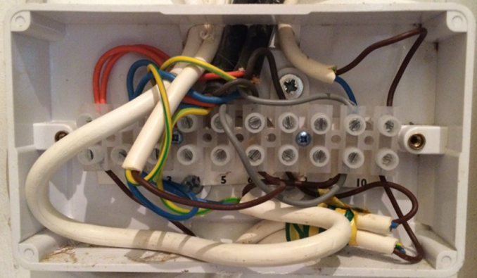
…and that’s when I saw this disappointing rats nest, which I can only assume had been passed as satisfactory two years previously by the installation ‘engineer’. I wasn’t present when that happened, so can’t comment on the specifics of who did what, but what I can say is that if I had left this standard of work at a customers house in my Telecoms days, I would have received a richly deserved career altering reprimand.
Most modern central heating installations employ a junction box as a central distribution point (DP) for interconnection wiring linking a boiler, timer, thermostats and all the motorised valves. The DP’s are usually wired to industry standard schematics or plans, well known examples being the Honeywell Y, W or S plans. In this case the boiler manual provided all the wiring details necessary for the installation engineer, but which needless to say wasn’t followed. As far as I could see, the wiring was actually random.
As it turned out, the specific fault we were experiencing wasn’t caused by this rats nest, but in terms of reliability it wasn’t helping, given three wires fell out of the termination block during what you’ll understand was an extremely gentle process of inspection.
Looking at this particular system – the boiler is connected via four wires. Three supply mains (Live, Neutral, Earth) and the fourth wire (a boiler input) can be made live externally in order to fire it up. When fired, the boiler pumps out hot water on one main 3/4″ pipe which Y’s into two motorised 2-port water valves (known as diverter valves) – one permits water flow into the hot water system (HW) and the other does the same for the central heating system (CH). If both motorised valves are open, then both the HW and CH systems will receive hot water flow. The valves are controlled by 4 wires (and an earth). Two of these wires drive the motor to open it, a process that completes in around 7 seconds whenever live and neutral are connected to the brown and blue wires. As soon as the supply is removed the motor will automatically close, which takes 2-3 seconds and is quite audible. The other part of the motor circuit is a normally open switch mounted on the valve motor inside the valve body and connected via the orange and grey wires. This switch will close only after the motor has fully opened and so is used to fire the boiler, but only after the water path is ready.
The next element of the system is the wall mounted Honeywell ST9400C timer. Powered from the mains, this has two internal relay outputs that respectively go live to drive the CH or the HW systems (or both). When I first started looking at this, I had assumed that the timer was two years old given the installation date for the boiler… but on a hunch I checked online and found a way to confirm its date of manufacture. With the device in RUN mode, press and hold the “+” button (immediately to the left of the OK button) for 8 seconds. The code that appeared on this timer was 4109… meaning week 41 of year 2009. I assume that this ten year old timer must have been reused from the previous system.
In terms of a process flow, consider the scenario where the boiler is off, the two motorised valves are closed and the timer is switched off. The order of events required to fire up the central heating (CH) system will be as follows:-
- The timer generates a live on its CH output. This might connect via an in-line room thermostat switch (if fitted) to the CH motorised valve (note that all these connections will be made inside the DP box).
- Assuming the room thermostat switch is closed, then the CH output will activate the motorised valve and cause it to open (which will take around 7 seconds to complete).
- When the motorised valve reaches its fully open state, the internal switch will then close.
- The internal switch has a live on one side and the other side will connects to the “fire me up” input of the boiler.
- The boiler should then start.
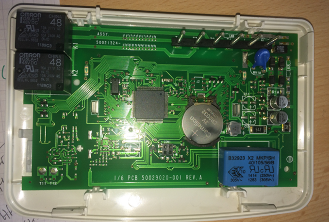
As there are two motorised valves, one for CH and one for HW, the two valve switches are wired in parallel so that if either one, or both activate the boiler will fire up. With a meter at the ready, I monitored the state of the timer CH and HW outputs and confirmed that the timer could switch either one live, but when it turned both on at the same time, the first would go live but the second signal (whichever one it was) wouldn’t. Unsurprisingly the two front panel LED’s were working fine but while the timer relays would operate individually they wouldn’t operate together… which suggested a problem with the power supply used to drive the coils. I separated the timer body from its wall mounted backplate and removed the back cover (involving pressing four snap clips) to expose the component side of the PCB. The sight of a whopping big blue capacitor told me everything I needed to know.
The timer is built round an Atmega3290V CPU made by our old friends at Microchip. Two 48v DC relays (top left) are used to drive the CH and HW systems. On the bench I found that when one relay was on, the voltage across the coil was lower than expected at 25v. If the 2nd relay was then turned on, the coil voltage reduced as low as 15v. Now, if you’ve ever worked with relays you’ll know that after being energised, it only takes a much lower voltage to hold… so the 15v coil supply was just enough to hold one, but not enough to energise a second.
The relay coil PSU was definitely the problem here…

© Verax Cincinnatus, Going Postal 2019
One of the main issues facing any designer of small mains powered kit is how to generate supply voltages. The most reliable option is to use a traditional transformer, bridge and regulator(s) but the size of these parts can be a problem for kit housed in a slim box. There is another option, involving a class of transformerless power supply that act like voltage dividers. Some designs of these use a high voltage capacitor directly coupled to the mains as a voltage dropper (refer to Wiki for more info hyperlink to https://en.wikipedia.org/wiki/Capacitive_power_supply) and which can be quite small in size depending on the selected capacitor. GU10 sized LED lights for example use these types of supplies because they can be shoehorned into the limited space inside the neck and body of the glass bulb… but if you’re aware of the paradox of very reliable LED’s that only manage to last 2 years or so whenever they are mains powered, you’ll immediately grasp the weakness here… and that is that these PSU’s don’t have a particularly long life span. Capacitors used in this way are directly coupled to the mains and so have to cope with all sorts of mains spikes and fluctuations (brown outs, power dips that sort of thing). The problem is that these type of transients have the effect of slowly depleting capacitor plate area, reducing the capacitance and consequently the PSU output. Over time, the output can fall low enough to cause a system failure… like ours.
There are additional complications with these power supplies as the lack of transformer means there is no isolation between the PCB and mains. Consequently some of the PCB will be live. For that reason these can only be used in a product with a fully insulated enclosure, such as the ST9400C. If you disassemble the enclosure you need to be very careful and you must hope that the designer has provided a resistive path to discharge the capacitor whenever the power has been removed. Otherwise the stored charge will be more than capable of giving the unwary a nasty belt. I remember some of the early cheapy night lights you’d likely find in a market would shock unfortunate users if they happened to brush against the live and neutral terminals after unplugging. That’ll explain why the sight of a large capacitor told me to take care poking around inside with a scope or meter, regardless of the board being powered or not! Make sure you do the same.
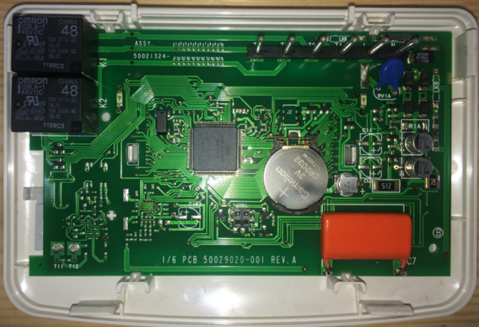
A new ST9400C timer isn’t cheap and so the fact that the PSU has a relatively short life span should have given Honeywell pause for thought. I am quite sure that 10 years ago it would have been possible to build a sufficiently small enough regulated 5v DC PSU, capable of satisfying the current demands of an LCD backlight, the relays and CPU with excellent reliability, albeit with more cost and obviously that would have been the deciding factor. As it stands, we can repair this timer because the plastic housing is trivial to open and getting at the capacitor (red arrow) without damaging the PCB is easy. The original Honeywell part was a 680nF @ 305volts and so the simplest solution was to replace it with the highest voltage part I could get into the physical space and take our chances on how long it might last. Looking on the Farnell web site took me to a Vishay made DC film capacitor rated 680nF @ 400v and which is physically smaller than the original. The extra voltage rating may help provide a little extra headroom, at a cost of just £3. Assuming an extremely conservative two year lifespan, I ordered 10 years worth of stock… if that makes sense.

© Verax Cincinnatus, Going Postal 2019
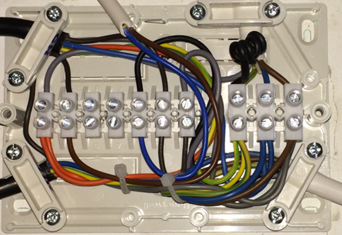
The final task was to rewire the rats nest left behind by the original installers and this time adhering to the wiring plan recommended by the boiler manufacturer. Electrically this doesn’t alter the system at all, but it will improve the long term reliability and help make future maintenance (or changes to the system) a little easier. The coiled black wire (top right) is a spare running from the DP up to the boiler and heatshrinked at both ends.

© Verax Cincinnatus, Going Postal 2019
© Verax Cincinnatus 2019 – first published on https://conehead.org/blog
The Goodnight Vienna Audio file


