The Doc’s ruby laser focused onto a lighter flint. The flint has been glued to the end of a match stick. The ‘explosion’ measures approximately 4 inches diameter.
Interesting things to note are the ‘candy stick’ diffraction pattern on the match stick – that is standing in a block of ‘foam packing’ material – from the focusing lens (see the set-up photo link).
The ‘1970’s top-of-the-pops’ red star burst around the focal point is in fact created by the iris inside of the camera lens at f26.
The most fascinating part is the way the white-hot particles of flint fork and divide. You can clearly see the bright nodes before they split into multiple paths.
A simple explanation could be that as a particle slows down and breaks apart more of the light rays are scattered towards the camera and so it appears brighter due to the long exposure.
Whatever the reason it’s a fascinating event to photograph and I never tire of the results.
Full resolution version here: https://imgbox.com/IAObd7bI
Lens and laser set-up: https://imgbox.com/nh87IK7r
Mirror Mounts And Eye Safety
A mirror mount for precision optical alignment needs to be ideally adjustable to within wavelengths of the light that it’s reflecting. Obviously a shaving mirror mount just wont cut it (an accidental pun!).
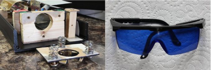
In fact they are very easy to understand and, luckily, easy to make. They are essentially a tripod turned on its side. Unfortunately gravity is now acting in the wrong plane. To get around this we use small springs to push on the ‘legs’ of the tripod. The above image is of the Doc’s output coupler (OC) mirror mount and it has been disassembled.
A ridiculously hi-res version (don’t ask): https://imgbox.com/y92BTGcH
Self-tapping screws run through the centre of the springs (from an old computer keyboard) which are then screwed to the main assembly – the piece of wood with three holes in it attached to the front of the laser.
With a very small adjustment to those three screws a precise alignment of the front ‘baffle board’ (to which the OC is fixed) can be made.
The bottom screw adjusts the vertical tilt while the top two the horizontal. Laser safety is the number one priority. There are no excuses (or forgiveness) for stupidity. Low power laser safety glasses are now incredibly cheap. The above pair cost less than three pounds from eBay. So definitely no excuses and far better than nothing.
Pick the opposite colour to the laser light you’re working with. So for red lasers you want blue or green. Note: these cheap glasses are for low power lasers only and you certainly cannot stare into the beam directly while wearing them. Ruby laser glasses are very expensive – second hand!
Another advantage of safety glasses are the improvements of contrast and less eye strain. It makes interference patterns clearer and therefore you get a better mirror alignment.
A Ruby Rod Holder
Before I can explain the Doc’s mirror alignment technique we need to just have a quick look at what’s holding the ruby rod next to the flash tube and the general setup.
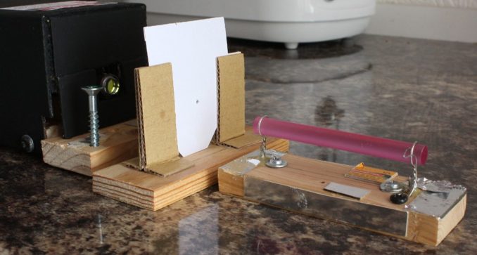
In the above photo we have the alignment laser, a screen with a small (1.5mm) hole drilled into it and the ruby rod sitting in its mount. I’ve removed the ruby and its mount from the laser cavity for photographic purposes. Obviously it will be inside the laser when we are doing the alignment.
This mount is a messy affair. It’s simple though, and that’s good, as it is quite an annoying problem.
Hi-res version of the ruby rod mount: https://imgbox.com/Otsbv6Dg
It consists of a small block of wood and two ‘loops’ made from 22SWG tinned copper wire. These are then soldered and screwed down and a small amount of epoxy glue applied to make everything reasonably firm. The aluminum foil deflects heat from the flash lamp. A small piece of steel wire presses against the rod and that helps to hold it in place.
The advantages of this simple arrangement are:
1) The thin wire loops block a minimum amount of light from the flash tube.
2) Its easy to adjust. Just bend the wire loops to move the rod left or right and use small pieces of paper or cardboard to lift either end of the wooden mount to make the rod level.
3) It’s plug-and-play! Having two ruby rods makes the interchangeability relatively easy.
The little white cardboard screen is very important. If you recall from the previous article I have glued a similar screen to the front of a diode laser. When aligning optical components reflection is a key aid. Trying to see a reflection directly on the face of a laser mirror can be very difficult if not dangerous. You’ll see it in action below and in the next article.
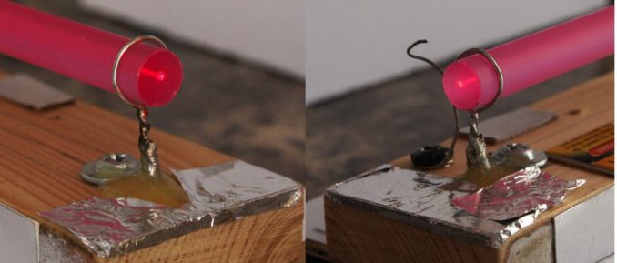
In the above photos I have placed the ruby into the beam of my He-Ne alignment laser. In the image on the left the laser spot is almost central. It does not have to be perfect. So long as the laser beam exits the ruby in the same position (right image) all is good.
This is proved by the photo below:
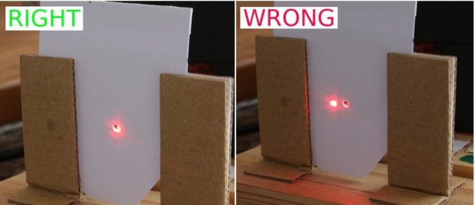
Unlike with politics, the left is right and the right is wrong! In the left hand image the laser beam is reflected from the face of the ruby almost completely back through the small hole. On the right the reflected light is skewed to the left indicating that the ruby rod is horizontally twisted in the laser beam and needs to be adjusted.
When we get the image on the left we know that our ruby rod is perfectly inline with the aligning laser beam.
Extra Thoughts
In the next article (aren’t you lot lucky!) I’ll describe my ‘four step’ mirror aligning system, finally.
I should also write about making a simple reflective housing that the ruby and flash lamp sit in. That is if the Doc can muster up enough energy!
I’m not repeating the links this time. They’re easy enough to find on the previous articles. Just type ‘ruby laser’ into the GP’s search box.
© Dr Mike Finnley 2018
Audio file