

More information on laser speckle can be found here: Speckle pattern
A Mirror Alignment Tool
The most important part of constructing a ruby laser (or any laser with external mirrors) are getting the mirrors alligned parallel with respect to each other. If they are not your laser wont work. You might be pumping enough energy into your crystal to make it lase but without near perfect mirror feedback you’ll never know.
The ingredients for this most essential device are: two pieces of wood, three wood screws and a cheap red laser pointer (or a He-Ne laser). You don’t want a blue or green laser because the ruby crystal will absorb those wavelengths and make the alignment difficult if not impossible.
Before we move on, the astute amongst you (and I know that there are many on GP) may have noticed a small contradiction or paradox.
How can the world’s first laser have been built if it needs a laser to align its mirrors?
The answer is that there weren’t any external mirrors on the first laser. The ruby crystal had its end faces layered with a silver metal coating and the output face had a small hole in it to let the laser light out.
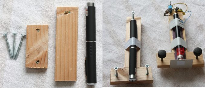
The items in the above image on the left should be assembled to form an approximation of one of the devices on the right (ignore the two fancy screws at the front, they do exactly the same thing as good-old-fashioned wood screws).
If you don’t want your expensive kitchen work top scratched I suggest filing the tips of the screws flat. Note the white card ‘screen’ glued to the front of the laser in the far right image. I’ll come back to that in part 4. Use electrical tape to hold the laser onto the mount and to also keep the power switch pushed down.
What we’ve made is an adjustable tripod for our alignment laser. We want to make the laser beam parallel to the surface that the tripod stands on. We now need a very flat surface that is not necessarily level with the ground!
A kitchen work surface or a piece of thick MDF (18mm) will do the trick. Its size will depend on the size of your laser and how accurately you want to align the mirrors. The greater the distance between your alignment laser and your laser’s mirrors the better the accuracy, but the more difficult to get a work surface that’s completely flat and the greater the beam’s divergence will be.
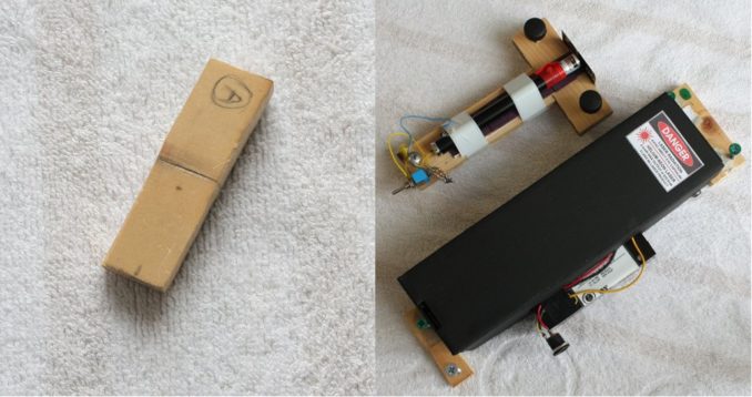
Before we align the laser’s mirrors we must align the alignment tool! To do this we need a small piece of wood. In this case about 2 1/2 inches by 3/4 inch square, see photo below, left.
Leveling The Alignment Tool
First we need an absolute reference for the whole laser system. The center of the OC (output coupler) mirror is the obvious choice and all the alignment instructions that follow will assume it to be so. It is necessary, therefore, that the OC mirror be easily removable from its mount.
The first thing to do is to point your leveling laser at the OC mirror. Adjust the three tripod screws until you have a spot reflected from the approximate center of the mirror. See photo, below.
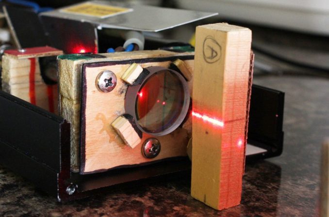
Insert the ‘block-of-wood’ into the laser beam and mark a pencil line where the beam intersects. We now have a ‘reference mark’ and can now proceed to ‘leveling’ the alignment laser itself.
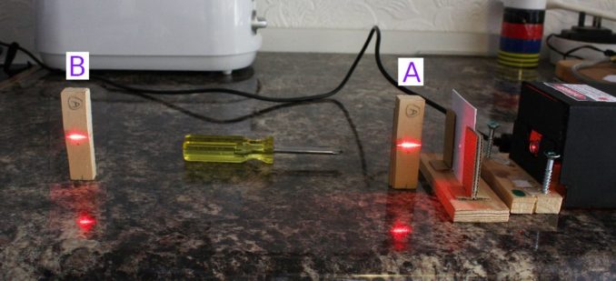
Referring to the above photo (a double exposure), start with your reference (block-of-wood) at point A. Adjust the two front screws ONLY until the laser beam intersects the pencil mark. Don’t adjust the back screw! You’ll be from here to eternity trying to level it otherwise.
Now move the reference block to point B and adjust the back screw ONLY until the beam intersects the pencil line. Repeat this process (from A to B and back again) and within a few repetitions the laser beam will need no more adjustment. It’s now parallel to the work surface and it’s center to the OC mirror.
The distance between points A and B should be the entire length of your optical work surface.
Thoughts and Links
Some might argue: What’s the point of making the alignment laser beam parallel to a work surface? It’s all relative anyway as the laser beam is a straight line.
Yes, but this way we’ve eliminated one axis – the vertical. We now have an ally and it makes the alignment process a whole lot easier.
In part 4 I’ll explain (or at least try to do so) how we can use this simple tool to make two mirrors almost truly parallel. It is in between such mirrors that quantum magic happens.
* * *
Here are some interesting links (again):
An article from Practical Science 1964. Unfortunately page 2 doesn’t work but the others are OK. Arthur Schawlow (see part 1 for who he is) wrote a great description of how the ruby laser works on page 3.
Modern Mechanix: Build your own LASER!
Sam’s laser FAQ has got to be the first stop for any amateur laser constructor. Detailed site with lots of information. Great fun and Sam is always open to the odd email.
Diane’s site is fascinating. A very clever person.
Don’t be put off by the name of the site or the fact they’re Russian. The translation is good and the projects are genius. Even if you don’t like lasers check out his gas jet engine at the end of the page. Gotta build one!
A good source of optical components are Thor-Labs. A great customer service and a box of sweets with your order too!
Thorlabs Inc.
© Dr Mike Finnley 2018
Audio file


