Introduction
In my laser articles Iv’e often mentioned the helium-neon (He-Ne) laser which I have used to align the feedback mirrors and make holograms. I thought that it would be remiss of me not to write an article describing this marvellous little device. In it we’ll play with light polarisation to demonstrate how sunglasses work. So here goes…
History
The He-Ne laser is my favourite. It was the first laser that I “built” (with a surplus tube). I remember saving up my money to purchase all the bits – the tube being the most expensive. I also remember the first power-up and thinking, “is this thing going to blow up?”. I took it outside(!) to try it. I switched it on…there was a pause as the power supply charged (it seemed to take forever)…a soft *click*…and there it was. A beautiful red spot of light. Magic.
The He-Ne laser is one of the most mass produced. Its reign spans from the late 1960s all the way to the late 1990s when visible semiconductor lasers became more affordable. It was invented by Ali Javan (and his team) at Bell Labs on December 12 1960. It apparently cost two million dollars to develop! It’s the world’s first ‘continuous wave’ laser rather than pulsed.
The first He-Ne laser worked in the infrared part of the spectrum and so the light was invisible to the naked eye. To demonstrate his laser, Javan came up with an ingenious idea that paved the way for modern communication systems. He connected it to a telephone line! Perhaps using some sort of modulating audio transformer wired in series with the laser tube, or a modulated mirror system. By placing an ‘optical detector’ in front of the laser (at some short distance) he was able to demonstrate that the audio from the telephone was indeed being carried by the infrared beam. Bear in mind, this was before fibre optic cables were even dreamed of. Genius!
tI’s been used in early laser disc players, printers, bar code readers, telecommunications, surveying, making holograms and many more applications; some that I’m unaware of. As I wrote at the beginning: a marvelous little device.
Tube Construction

As you can see in the above photo the laser mainly consists of two glass tubes. An outer tube (called a gas reservoir) and the inner ‘capillary’ tube. This is where the lasing takes place. The gas reservoir contains the bulk of the helium and neon gas mixture of something like a 5:1 ratio. Remember a laser needs a ‘pumping medium’ and a ‘lasing or gain medium’. In this case neon is the lasing medium and helium the pumping medium.
The He-Ne laser is a four level system. The excited helium electrons ‘kick’ the neon electrons up to a level 3 orbit (counting from zero). These electrons (in a now unstable state) then ‘fall back’ to level 2 where stimulated emission occurs (laser light). The electron continues to fall from level 2 to 1 and emits spontaneous light. Finally the electron falls back to its ground (stable) state (0) and the cycle starts again. Remember, four level lasers are efficient – well almost. The poor He-Ne requires tremendous amounts of optical feedback from its mirrors. 99.99% for the HR mirror and 99% (Yes, that much!) for the OC. This means that He-Ne lasers range from about 1mW to about 25mW. Compare that to, say, a CO2 laser of a similar size pumping out many hundreds of Watts.
An interesting and important device is the ‘getter’. It’s usually a little metal circular ‘trough’ that contains various powdered metals such as magnesium and aluminium among others. During tube manufacture this ring is ‘zapped’ with a high power RF signal causing it to heat up and deposit the mirror finish on the inside of the tube. Its purpose is to ‘soak up’ like a sponge any remaining oxygen atoms inside the tube. You might have seen them in old radio valves. The perfect silver coating turns to a white powder if air gets into the tube – so a nice mirror look shows a good air tight seal.

In this photo Iv’e zoomed in on the ‘Brewster polarising window’ contained inside this tube (the little circular glass disc). It blocks unwanted light (say the vertical) and passes just one plane of light – ideally. Okay, it’ll be easier to see practically than that gobbledegook I have just written. Before we do let’s look at my Melles-Griot (I think that’s how you spell it. Pronounced ‘mell-iss gree-oh’ again, I think!) non-polarised He-Ne powered up:

First thing to note is that the OC and therefore the laser light emerges from the cathode whereas the Philips tube has the light coming out from the anode (which is the usual method). As far as I’m aware it makes no difference (just the HR/OC on the other end of the tube) but experts at MG perhaps know different.
The other two things to note is that the plasma discharge occurs only in the capillary tube while the gas reservoir stays out of it. Think of the reservoir as the chill out lounge for the helium and neon atoms to relax before they join the party again! The other thing to note (green arrow) is the light leak from the HR mirror. It’s faint but you can just make out laser light emerging from the 99.99% HR feedback mirror. Proving that no mirror is perfect.
Sunglasses And Polarisation
I’m sure that we’ve all heard of the Polaroid company, famous for cameras and sunglasses.
When we look at light bouncing off objects around a room most of it will be ‘randomly polarised’, i.e if you put on a pair of polarising sunglasses almost everything will look the same (albeit duller).
So what do polarising over basic sunglasses do other than make the scenery look duller? They’re designed to block the horizontally polarised light. Why? Well imagine you are driving along a road and there has just been a heavy shower. The sun pops it head from behind a cloud and you get dazzled by the glare from the wet road. That glare is mainly horizontally polarised light. So you reach for your expensive Ray-Ban sunglasses and voila the glare has gone as the optics in the lenses are biased to vertically polarised light.
Let’s see that in action with my trusty He-Ne and an old pair of late 1960s Polaroid sunglasses.
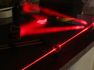
In the set-up below you can see the laser (L), the pair of my dad’s old Polaroid sunglasses and a small piece of diffraction grating (DG) that I made with my holographic kit – It’s not very good but it will do. You can see the laser light passing through the sunglasses and the DG. The beam then travels about six feet to a paper target so we can see the results.

Note that Iv’e turned the sunglasses through 90 degrees so that the vertical is now horizontal and horizontal is now vertical – come on, it’s the Doc and his wacko ideas! No, there is a good reason: my diffraction grating is rubbish and seems to work better in the horizontal plane. So the horizontal light from the laser passes through the vertical filtration of the lens. Anyhow, here is what the output image looks like without the sunglasses:

Note the two bright ‘satellite’ spots in the horizontal plane (green arrows) and also note the noise in the vertical plane. That’s the noise we want to get rid of.

Remember that as Iv’e rotated the lenses 90 degrees the horizontal blocking of the glasses now blocks the vertical light. As can be seen the Polaroid lenses are blocking the vertically polarised laser light and allowing (with some loss) the horizontal light through. Obviously when the sunglasses are perched on your nose it’ll be the horizontally polarised light that is blocked and the vertical allowed to pass through.
Some may argue that I should have rotated the above images 90 degrees to make this article easier to understand. Where would be the fun in that say I? Anyway, you should not fake the data in any science experiment – however confusing it might turn out. Well that’s my excuse.
Conclusion
I suppose the number one conclusion most of you will take from this is: don’t try and follow any of the Doc’s experiments as they’re all screwed up. That being said I hope you get the idea!
I’m currently working on a simple electrostatic generator machine which might be fun. I’m also working on another Admiral podcast. Perhaps an Alfred Hitchcock Presents type pastiche but I haven’t decided yet.
Well, that’s that for now so all the best and cheerio.
© text & images Doc Mike Finnley 2023