Part two, How To Drive a (Model) Train
Welcome back to the sleepy town of Dingleberry, “somewhere” on the UK rail network, a destination found only by the terminally lost and those who were foolish enough to accept advice from the ticket office.
In this episode we will consider the subject of actually making a model train move, which can be straight forwards or slightly more complicated – you may be able to guess how I do this…
Putting the Fun! Into Fundamentals!
Firstly a quick look at what a model train actually is maybe useful, here is one of my Class 86 with her clothes off:
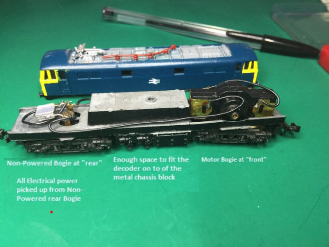
She is a somewhat elderly lass but reasonably typical of how these things work internally. To the right there is a small DC electric motor, designed to run on a 12v supply – you control the motors speed by varying the voltage, less volts, lower speed – but also critically less power which matters, on this more shortly..
This locomotive has electrical pickups just at the other end, this takes the electricity from the two rails (I’m not modelling and not massively interested in other electrical schemes but suffice it to say there are many, third rail things, overhead pickups that work etc). This is carried by the two wires to the motor. The rectangular silver thing is a capacitor, this is used to reduce electrical interference on TVs and radios, the loco will run without it if you want to annoy a neighbour.
To drive this you place the locomotive on the track and apply between zero and 12 volts, to go the other way you swap the wires over.
As noted above the problem is at low speed you have very low power as essentially that’s how you are controlling the speed, hence the habit of model railway locomotives to not want to run at low speeds and in the case of this one, not run at all until about 7 volts are provided, and not stay running until about 9 volts are present (newer models are better at this).
Every method of driving the train involves this simple operation, change the electrical power to the motor and you change how the motor runs.
Old School
The simple way of controlling this is a method that used to be very common, and it is extremely simple.
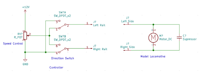
The diagram above shows how this works, you start with a 12v DC supply, usually from the mains through a transformer and rectifier (which is why these things used to be quite heavy), there is then a rotary dial or slider connected to a variable resistor – this controls the speed by providing an output voltage that varies from zero to the full 12v.
The switch is there to change the direction of travel.
And that’s about it, this will provide 0-12v with the ability to reverse the polarity and thus easily defeat the Daleks and drive the train.
This is somewhat crude, there is always electrical current flowing so the controller gets a bit warm (basically what is not going through the locomotive is going through the variable resistor), as such a number of controllers had a few more features, to name a few:
- Including an “off” switch, often into the dial so you had the option to cut the power completely when stationary.
- “Lo speed” mode where another resistor was switched in to limit the maximum voltage and power to the track, I never did get one of these to work right as its a “trainset” thing for when younger kids are playing, trouble is it cuts the power so much the things hardly move
- Soft Start/Stop, by adding a capacitor or two you can provide for gradual acceleration and braking, often with a switch to enable or disable it – again results vary on how well these work.
There is also another method called a “back-EMF” drive, this tries to get around the issue of the train not moving well at low speed. This magic is performed by having additional circuits in the controller, these will cut the power to the motor at intervals for very short periods, this won’t stop the motor due to SCIENCE! But it allows measurement of the reverse electromotive force, which in effect allows measurement of the speed in the motor by measuring its performance. These controllers then take this knowledge, combined with the users desired speed and adjust the voltage, thus you may say “go at low speed”, the controller will increase and decrease the voltage until the train is doing this.
This can work well or badly depending how it’s done, often this can be enabled/disabled with a switch and on more advanced controllers the “amount” of extra power can be set with another dial as every locomotive is slightly different.
More Modern
There is another way to drive one of these locomotives without changing the locomotive, this is to use a digital technique called pulse width modulation. There you apply either 0 volts or 12 volts to the track, and alternate between them quickly (as in thousands of times a second). This means when powering the motor it gets the full power but only for part of the time. The result is much better control at low speed, but can be a pain with older motors not really designed for the full 12 volts at all times so they get a bit warm.
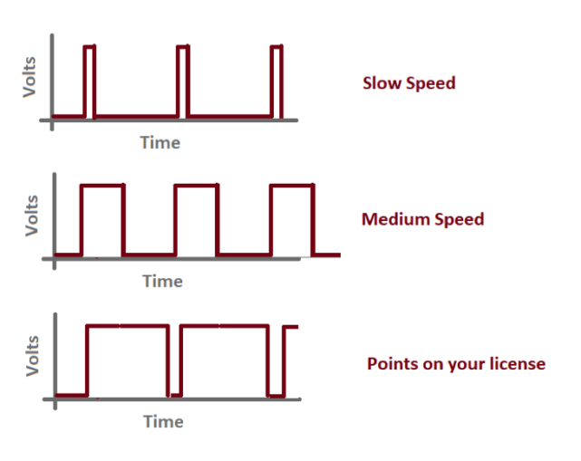
Above shows roughly what’s sent to the locomotive, again to go the other way you just swap the wires.
There are several ways of generating an electrical supply that can do this, for Dingleberry I made a simple controller to allow me to test locomotives by using an Arduino microcontroller, a variable resistor so I had a speed and direction input – using the midpoint as “off” then turning to either side to set the speed and direction. This was used to drive a microchip designed to generate the PWM waveform and amplify it and able to invert it nicely for me.
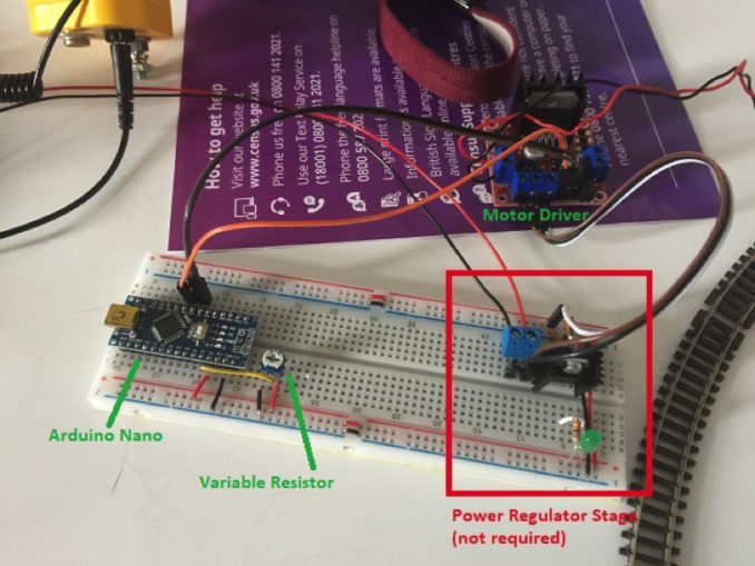
This is the contraption created, it’s crude but it works. Takes a 12v supply, there is a circuit on the right to generate the 5v the Arduino likes, the module to the top right is the motor driver, a commercially bought module that cost about a fiver.
This is controlled by some basic code that repeats a cycle over and over:
- Measure the user’s input
- Tell the motor driver what to do
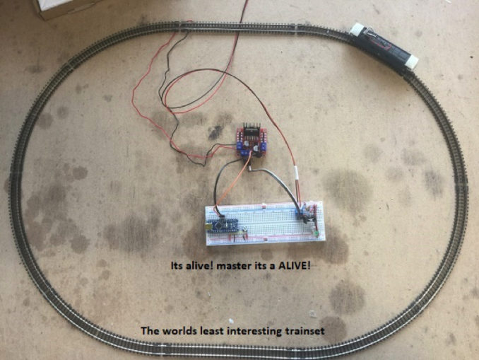
This is crude, but it works, by using the Arduino and motor shield you can also put in things like soft start/stop quite easily, it’s just a code change, likewise speed limiting is also pretty easy to do. It would not be too hard to add a speed display and similar but I didn’t feel the need (yes, for once I avoided adding a needless complication).
At some point, I need to put that into a little box.
This control method is simple but has a huge limitation, you are putting variable power to the rails, any locomotive on the track will respond to it – traditionally this has been managed by using switches to isolate various parts of the layout (often built into the model railway turnouts, or points, themselves) so for example, a train in a siding doesn’t move because it’s got no power while one in another siding can because it has the power.
The wiring for this can get complicated, often known as “cab control”, where you can have switches that for a given section of track can say which of several controllers it is connected to, or isolate it totally. For many years this was basically how model railways worked.
And this is how, in the old fashioned world of “Analogue” you drive a model train…
In Part three I’ll have a look at how Dingleberry is actually going to be controlled, Digital Command Control or “DCC” which takes this motor control and Arduino, makes it a lot smaller and puts it inside the locomotive, then sends it control signals over the track from another computer allowing the removal of the various switches as now you can talk to individual locomotives, and with some systems they can even reply.
© Copyright text & photography Leopard 2021
The Goodnight Vienna Audio file