
As mentioned recently, I’m building a new model railway. The baseboard dimensions have been confirmed – a number of sections, each 40 inches x 23in as these can fit into a cupboard for storage. At the moment the plan is to go with up to six of them in total, making an O shape layout with a gap in the middle.
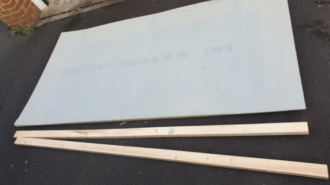
The sections are made of 2×4 cls timber – the commonly available beams used to make up partition walls. These will mainly be topped with Sundeala K board. This is more expensive than chipboard or mdf, but lighter and easier to work with – it’s more akin to a pinboard so using nails or cutting sections out is better and it does not transmit sound as much as the harder boards.
Finding the stuff was more of a challenge, a sheet of it measures 2.4m x 1.2m. That is enough for four of those sections- at £75 a sheet, that will be enough to be getting on with. It is not generally available in builders’ merchants or the local B&Q and posting something that size is pricey. Having rung round the local wood yards and been unable to find a cheaper non-branded substitute, I found the local Jewsons did actually stock it. They obviously don’t sell much of it, judging by the dust on the thing and by the looks of it – a use by date, but got it home on the roof rack, supported and braced by aforementioned timber beams.
© Sweaty Dave, Going Postal 2020
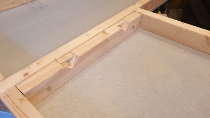
The next stage was simply a case of cutting, screwing and gluing the beams into square sections, using the board to ensure they were true. Getting each section to line up with the neighbouring one is important as train tracks have to be aligned precisely every time to avoid derailments.
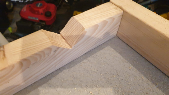
The sections are to be bolted together which will hold them in place but getting the alignment is said to need a bit extra. The recommended way is to cut two triangles out of one of the sections and fix part of that offcut to the other one – when put together the cut board drops into the triangle thereby ensuring alignment.
© Sweaty Dave, Going Postal 2020
© Sweaty Dave, Going Postal 2020
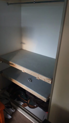
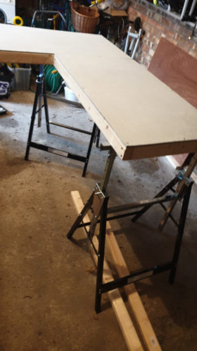
Two made now, I think I’ll do a couple more but as you can see, they fit into the cupboard without any problems. I’m loathed to add fitted legs, so I am searching for some trestles to stand them on.
© Sweaty Dave, Going Postal 2020
Lo and behold – I don’t know how they do it, but there you go – Aldi selling heavy duty trestles for £12 a go. I’ll get four for now – as once they’re gone, they rarely return and finding something that matches would be nigh-impossible.
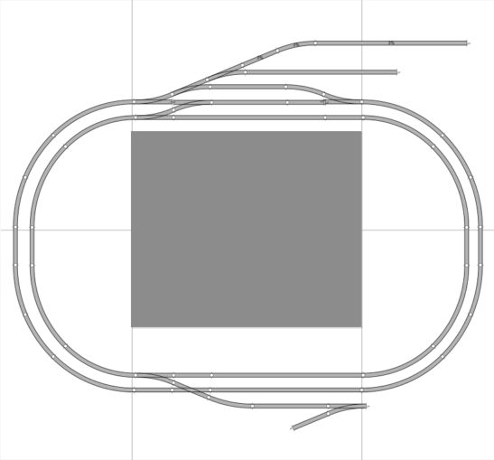
The track design is starting to come together. It’ll build up over time – I’ll start with the first four sections build upon them. The beauty of this approach is I can just work on an individual section on the desk rather than stooping over the entire layout. Where the track crosses the joins needs to be as simple as possible – no points straddling the gap or curves if possible. In the worst case, track pieces will have to be fixed down then cut at the join. I designed it with Peco Setrack in mind, looking to have radius 2 and 3 curves – nothing too sharp which would both look wrong and cause some locos problems.
© Sweaty Dave, Going Postal 2020
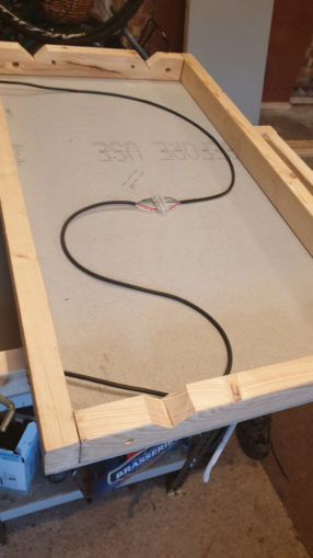
Power to each section will have to be made through plug in wiring so it can easily be built up and broken down.
When building layouts there are two options for powering everything. The traditional method, and the one used on the last layout, is for 12v dc – one side is +ve, the other -ve. This has been a standard since the 1940s. Before then it was mains power in the tracks – ah the dangers of childhood in Bobo’s time!
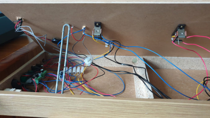
With 12v you have a sliding scale – 0 volts in a section of track and nothing moves, up to 12v and everything on there moves. Small starter layouts could be run from a battery with one + and one – connecting to the track and easy to understand. To have more than one engine running under control at one time is done by individual sections and powering them separately – e.g. two loops of track, one up, one down, each powered in isolation. Points where the two loops join or in sidings are isolating – they only feed power in the direction the are set which further allows for engines to be controlled – run one into a siding, change the points and it is isolated, meaning another one can then run. Any other accessory such as a point motor is powered separately, usually wires running from a board next to the controller. It does lead to a lot of wires and easily gets messy – this is the mess under the covers of the shunting layout with power individually going to cyclists, four points, three lampposts and the crossing lights as well as the track itself.
© Sweaty Dave, Going Postal 2020
In the 80s, when home computers got going and the technology moved on, Digital control came to railway modelling. Rather than 12v DC it uses 16v AC. So what you say? Similar to a computer network, there is a constant level of power running through it, which provides the juice but also sends messages to each device. Each device needs a decoder to understand the messages, so a little more expensive. The power is always on, going to all aspects using the same wires – to all the track, sidings and also to small controllers for points, signals etc. The power being on means carriage lighting and header boards can be lit constantly and all the power and messages are fed from the same two wires. To start an engine, the controller sends a message to that engine, a chip onboard then recognises the command and acts accordingly. That can include how quickly to accelerate, even sound if you pay enough for the chip.
12DC controllers are very cheap – simply variable transformers. You can pick one up for £30 or less. DCC controllers are microprocessors so a lot more expensive – even a basic one will cost over £200 new. I followed a few second hand ones on ebay, but even those (PCC Powercab) were selling at around £120+ a time.
I finally found an alternative – a bloke selling basic Arduino controller for £50 that then links to your phone and you control the trains using your phone. With the phone doing much of the processing, the controller is a lot cheaper so have ordered one of those.
So a few things going on at the same time – Baseboard construction, track design and power decisions.
Back to baseboards, that sheet of sundeala was big enough for four sections – which is enough for now. Rather than buy another board, if and when I get to doing any more, I’ll forego flat board and build them as open sections – you create a plank for the track to cross, the rest of the area being built up above and below track level with scenery.
© Sweaty Dave, Going Postal 2020
With the layout in sections, they need to be connected in a way that gets the power to all areas. Hoping the tracks touch at the joins isn’t a solution, so each section needs to be fed power.
I’m going to fit a couple of 5 pin din plugs (as you used to get on your old stereo) to each section and chain them up together as a power bus. As long as each is wired consistently it should all work! Two of the pins will be for 16v AC wires. I will add a couple more at 12v dc for any lighting or other accessories. Each 5 pin din socket will connect to a terminal strip then on to another 5 pin din socket to the next section using 4 core low voltage wire, commonly used in the automotive sector. After the spaghetti of the last layout, this will be a lot neater – colour coded with blue/yellow for AC and Red/Black for DC. Each one will have a junction box/set of connectors to supply the power.
The wires have arrived – 4 core from din plug to terminal strip then individual wires from there to whatever needs them – lots of fiddly soldering as the wires are really a bit thicker than the Din plugs are designed for but we’ll get there.
© Sweaty Dave, Going Postal 2020
I’ll start with a section that is going to be a coalmine. It’ll need a winding engine house/boiler house, a pit head winding tower and structures over the tracks that provide coal drops. There are always a jumble of other buildings around such places, so a few kits buildings will be a good start. Add an exchange siding (for handing over trucks from mine to railway company) and run around for arriving and departing trains, and most of the baseboard will be taken up! There aren’t many ready made mine buildings on sale or in kit form, so will be looking at Plasticard and painting. eBay is available to supply sections that are scale i-beams and other girders – that sounds like a job in the Christmas holidays.
To get the latest info, I’ve ordered a PECO catalogue – they don’t change much but the last one I have is nearly 20 years old. That’ll give me the available track options to choose from. More about the track in the next instalment.
Next time: All about the track. Starting a test run.
© text & images Sweaty Dave 2020
The Goodnight Vienna Audio file


