I know it has been remiss of me for not following up on the article of 16th of January. I’d planned to write one around once every two weeks as the layout progresses but time marches on..
Before I start, I do thank you for your kind comments last time, and long memories. Even requests! For Grumpy Angler, here is Jeremy Vine doing what he does best..
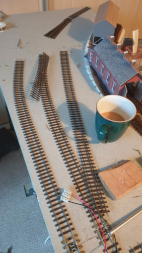
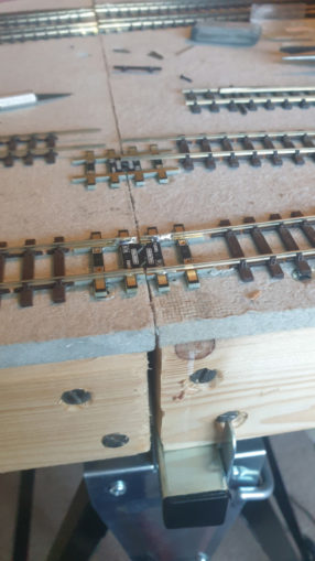
Back to the current layout – it is progressing, just a little slower than expected. The tasks that need doing at the moment are fairly repetitive and mundane – cutting track at the edge of the board, gluing a plate down then soldering the track to it so when boards are joined the track doesn’t need to be joined by fishplates or anything fiddly, it simply should line up perfectly. It is time consuming but not that visually interesting.
There are one or two products to help you in this task – as noted last time, I bought a pack of Pro-track rail aligners. £10 for four pairs of mouldings in the shape of final sleepers, topped with copper, to which you solder the track. They are well thought out and constructed with holes for nails, and others to let you feed power in using tiny wires.
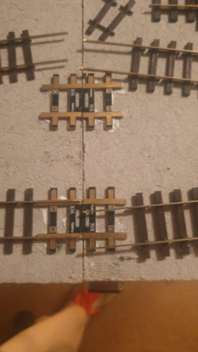
They’re not a connector as such, more like a couple of jigsaw pieces, the two not making an electrical connection, just ensuring the track is properly aligned. You glue them to each baseboard in the right spot, add a nail or two if needed. Once dry, trim a couple of sleepers off the track and solder it in place.
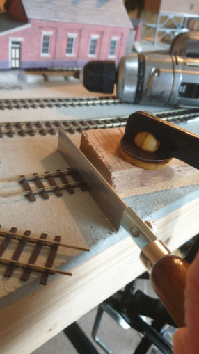
Make sure the track is fully sorted at the other end before doing anything and trim off any excess once it is in place – best to clamp it down sandwiched under a block of wood to avoid breaking the solder when cutting.
That check of the other end is an expensive one if you cut the track then realise the other of that piece isn’t actually fully connected to the next bit – too late to shove it up. Unless the boards are separated it’s no good trying to use a Dremel as it’d give an angled cut. I bought a razor saw – a very fine toothed saw to make the cuts – I guess a hacksaw/junior hacksaw is an option with a very fine toothed edge otherwise the rails are just ripped sideways out of the sleepers rather than cut.
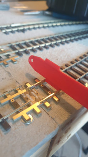
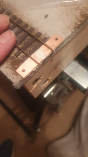
The layout I have probably has over 20 such joins – so it’d be at least £50 just on these small aligners. A budget option is to make something yourself. Cutting a strip of PCB board (one side copper plated) gives you a cheaper option – boards cost about £7, measuring 10x 22cm, from which you can make say 20 fixings of 1cm x 5cm (if you can saw in a straight line! The bonus here is a number of the lines on this layout commit the cardinal sin of crossing a boundary on a curve not straight on. That’s something the aligners can’t cope with, you have to be square for them. Instead it needs a longer skewed fixing point. Each chip sized piece is cut out, a couple of 1mm holes drilled, one each end then it is glued flush to the baseboard edge and a small tack used each hole to further ensure it does not move.
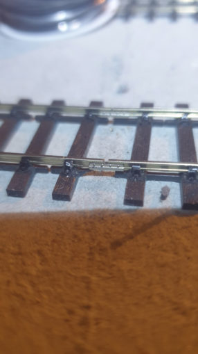
This work does then mean that each small section of track will need to be wired up to provide power as it can’t jump the gap. In addition each point has to be insulated. That is due to the crossing point being ‘positive’ for say the left track and negative for the right – one way the left wheel uses that bit of track, the other way the right one does. As throughout the track the left wheel is positive and the right is negative this does mean a bit of additional complexity for the points – insulated joiners to each of the possible routes and having those powered sorts it out. A couple of 2mm drill holes between the sleepers is enough to give space for power wires peeking up, soldered to the track.
For those of you with expert knowledge this is a Digital control layout, so AC rather than DC but the avoidance of an electrical short still applies, it’s just easier to explain in those terms.
So lots of fiddly technical stuff. To help in this task I have finally bought one of those ugly headsets that have a head torch and magnifying lenses to see this stuff. Not the most comfortable item of headwear but very useful when working in badly lit areas.
I’ve set up the exchange sidings/loading road for the coal mine but not yet glued it down – the Y point at the end now has holes drilled to allow space for a solenoid.
Once the rails were cut to length, and my new vision meant I could align them to fit together then an electrical test.
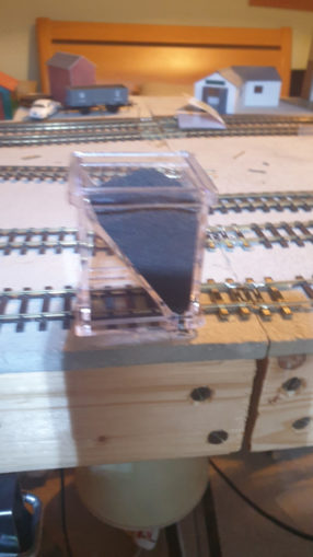
It shouldn’t need to be lifted again, so to break the monotony I decided to try out a new toy – a ballast laying device, basically a small acrylic box with grooves in the base to follow the tracks and three holes to dispense ballast from the triangular hopper. I’ve not glued the track down, it is soldered at each end and the points are fairly well anchored with the point motors, so thought between that and a layer of glued ballast they’d be fine.
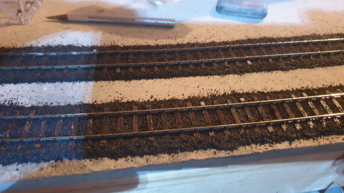
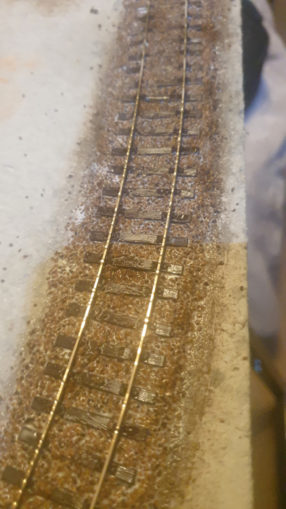
For the first two runs, under the coaling stage I opted to use ‘coal’ – near black tiny flecks as the ground would be coated with coal dust under these chutes. Fill the hopper, drag it over the track and by magic it deposits a near perfect amount of ‘ballast’ around the sleepers! I’ll be honest it worked far better than I thought it would – a rare nice surprise!
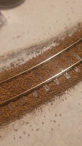
I dug out a strange looking paintbrush that has more of a giant cotton bud on the end rather than bristles – so more of a pad than a brush but enough to gently ease any excess ballast off the sleepers. Once in place you have to turn off the power and spray the track with a fine mist then use a 50/50 PVA/Water (with a spot of washing up liquid in to break the surface tension) and cover the ballast with it. Where the ballast is dry the glue simply forms a ball and rolls around picking up flecks. The spray breaks that surface tension and it instantly disappears into the dropped ballast. What white you can see from the PVA disappears when it eventually dries – the place was soaking!
Next day and indeed the track was fixed down and the ballast not going anywhere. It needs a quick hoover to remove the excess overspill from the surrounding area but that around and under the track is solid.
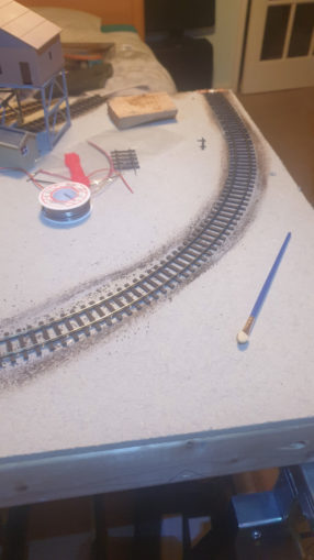
With that success I moved on to ballast the area in the branch line running into the siding. With it being further from the mine and hopefully eventually a bit greener, I opted for a green/grey ballast, giving it the same treatment and soaking. It’ll take a day or so to dry.
Next? I should wire up some of the bits between these two ballasted sections and then ballast them. Get that Y point motor in place and figure out how on earth I wire up the three way point!
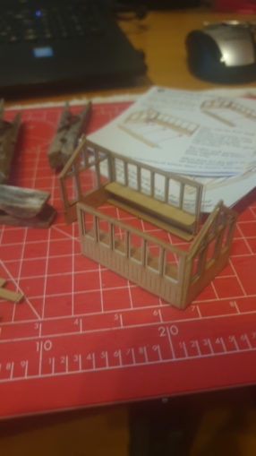
There has been a small amount of work building a Metcalfe greenhouse between working from home meetings.. that’ll not take long to finish.
© text, images & video Sweaty Dave 2023
The Goodnight Vienna Audio file